
A noisy valve is often described as cavitating before anyone records the liquid temperature, absolute pressures or operating position. That diagnosis can lead straight to the wrong replacement.
Cavitation involves vapour formation followed by bubble collapse as pressure recovers. In flashing service, vapour persists downstream. Distinguishing them requires fluid properties and a pressure-profile assessment, not noise alone or the catalogue pressure class.
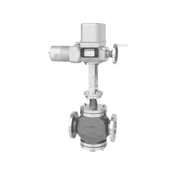
The lowest pressure may be inside the valve
The upstream and downstream pressure readings do not necessarily show the minimum local pressure as fluid accelerates through the restriction. If local pressure drops below the liquid's vapour pressure at its flowing temperature, vapour can form. What happens during pressure recovery separates the two cases.
Use absolute pressure when comparing with absolute vapour pressure. A gauge reading cannot be compared directly without accounting for its reference. Identify the fluid and temperature used to determine vapour pressure; do not insert a room-temperature water value for a hot or mixed liquid.
Spirax Sarco's water control-valve sizing tutorial explains pressure recovery and anti-cavitation trim principles. The method requires configuration-specific information; it is not an instruction to select a valve solely from its nominal size.
A deliberately simplified pressure example
The following values are invented for a conceptual illustration. Assume an unspecified liquid has a vapour pressure of 0.5 bar absolute at the stated temperature. No real valve or fluid is being sized.
| Assumed case | Inlet | Minimum local pressure | Recovered outlet | Conceptual observation |
|---|---|---|---|---|
| A | 5 bar abs | 0.3 bar abs | 1.5 bar abs | Vapour formation and subsequent collapse are possible |
| B | 5 bar abs | 0.3 bar abs | 0.4 bar abs | Vapour may persist downstream: a flashing case to evaluate |
| C | 5 bar abs | 0.8 bar abs | 1.5 bar abs | This simplified profile does not cross the assumed vapour pressure |
The table illustrates the distinction. It does not predict damage, flow capacity, choking, noise or suitability of an actual valve. Local pressure depends on the valve and operating point; it is not a number to guess during an engineering selection.
Record multiple operating points
Minimum, normal and maximum flow can occur with different inlet pressures, outlet pressures and temperatures. Review the actual combinations, including start-up and a defined upset where relevant. A sizing sheet containing one maximum-flow row may leave the damaging condition elsewhere in the operating range.
| Required input | Why it matters |
|---|---|
| Liquid composition and temperature | Determines relevant properties and phase behaviour |
| Inlet/outlet absolute pressures | Defines the operating pressure reduction |
| Flow and units | Identifies the duty to be passed or controlled |
| Density and viscosity as needed | Supports the applicable sizing method |
| Valve travel and proposed trim | Affects the pressure profile and operating range |
| Pipe sizes, fittings and layout | May affect the installed conditions and recovery assessment |
| Observed noise/vibration/damage | Helps diagnosis but does not replace the fluid calculation |
Use the selected manufacturer's configuration-specific sizing data and applicable method. A generic severity band or travel percentage does not establish acceptance for another design.
The corrective review differs for cavitation and flashing
| Finding under the actual operating conditions | Engineering review to request |
|---|---|
| Vapour forms locally and collapses during recovery | Assess the pressure reduction and recovery; investigate suitable staged/anti-cavitation designs and any approved system changes |
| Outlet conditions keep the liquid below its vapour-pressure boundary | Assess flashing flow, velocities, geometry, erosion-resistant construction and downstream piping |
Emerson's flashing explanation identifies the central limit: valve selection cannot prevent flashing while the defining fluid and downstream conditions remain. Hardware can instead be selected to reduce damage. This is why an anti-cavitation label alone is an incomplete answer to a flashing duty. Any process-condition change requires the responsible designer's approval.
A larger valve is not an automatic cure
An oversized control valve may operate close to its seat at normal demand, changing controllability and local flow conditions. A smaller valve may introduce too much loss or fail another operating point. The selection needs the complete required flow range and pressure conditions.
Likewise, hardening a surface can address a wear-resistance question without preventing vapour formation. A multistage or other engineered trim needs its own sizing and application evidence. Do not assume that a metal-seated isolation valve becomes an anti-cavitation control valve because its materials sound stronger.
The pressure class identifies a rating framework. It does not state a universal allowable operating pressure drop free of cavitation. Mechanical differential-pressure limits, flow limits and damaging-service limits should remain separate fields.
Turn a symptom into a useful investigation
For an installed valve, collect the actual tag/model, operating position and corresponding flow, pressures and temperature when the problem occurs. Record whether it appears during start-up, steady duty or shutdown. Existing inspection findings can help identify where damage occurs.
Do not open pressurised equipment or change critical process settings to gather a blog's example data. Investigation and any intervention follow the facility's approved arrangements. The aim here is to give the supplier and responsible engineer an adequate diagnostic brief.
Turn a proposed remedy into an accountable sizing response
If a supplier proposes staged trim or a more erosion-resistant construction, ask for the operating-point calculations and application limits that support it. The response should address capacity, usable travel, pressure recovery, phase behaviour and relevant velocities across the required range. Identify assumptions and any point outside the proposed design's limits.
Do not accept one universal cavitation-index severity table for every valve geometry. An index can be a defined screening input, while configuration-specific coefficients and method determine the applicable assessment. A generic boundary cannot predict an exact failure time.
Noise or bubbles can also involve mechanisms other than vapour-pressure cavitation, including release of dissolved gas or mechanical movement. Retain fluid composition, pressure-temperature history and observed operating conditions so the investigation can distinguish them.
The result should be a proposed construction with an identifiable calculation and limitations. A hard-facing label alone neither changes the phase boundary nor establishes that the complete system is acceptable.
Where a ZGV enquiry begins
ZGV publishes globe valve and butterfly valve references, among other industrial valve families. A catalogue entry does not establish that every configuration is suitable for continuous regulation or offers an anti-cavitation trim.
State whether the required job is isolation or control. Ask ZGV to identify an appropriate offered configuration and the sizing or application information available for the actual duty. If additional specialist engineering or a different construction is needed, keep that requirement explicit.
Noise may have other causes, including gas flow, mechanical movement or system vibration. Use the operating record to establish which mechanisms need investigation. The presence or absence of one noise description does not provide a universal cavitation pass/fail test.
Submit the operating-point table and symptom record so the reply can address the real pressure-recovery question, rather than an unverified cavitation label.
ZGV VALVE · Request a quotation · WhatsApp +86 13732021078
Download the ZGV valve RFQ template and attach your service conditions and required inspection documents.