
An event matrix makes automated-valve requirements easier to specify and verify. Define what the complete package should do when air pressure, electrical power or the control signal changes, including the required behaviour when supplies return.
Choose fail-open, fail-closed or another required state from the process safety and operating design. Then specify each triggering event, available energy, action time, feedback and restart behaviour for the complete valve package.
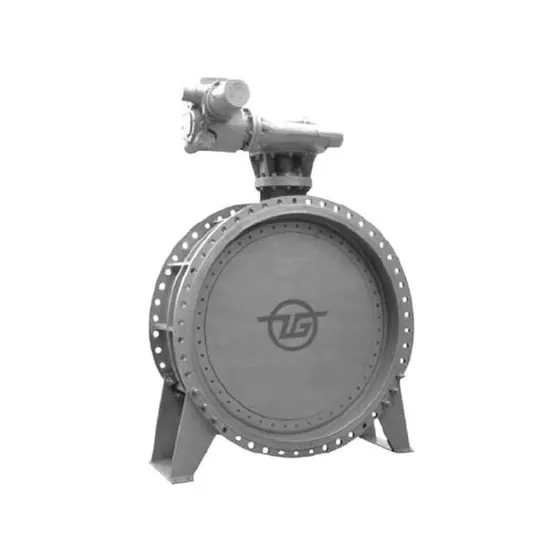
ZGV's catalogue includes pneumatic butterfly, electric butterfly and driven gate-valve references. These provide product starting points for an automated-valve enquiry, with the required event response, available utilities and feedback specified for the complete offered package.
There is no universally safe direction
Closing a fuel line and preserving a cooling path are different process tasks. Even those descriptions are too broad to approve a real installation: the site's hazards, connected equipment and control philosophy determine the required state.
Do not select failure action from a rule that every process valve should close. Likewise, do not assume that a double-acting actuator stays reliably in its last position after supply loss, or that every electric actuator closes on power failure. The complete design and accessory circuit need confirmation.
Rotork's fail-safe actuation article describes how different configured events and stored-energy arrangements affect its own products. It illustrates why the enquiry should state the event and response directly, rather than infer them from the energy source.
Separate normal position from failure position
A valve can be open during normal operation and required to close on a specified trip. Another can normally be closed and required to open on loss of a named supply. Normal position describes the operating arrangement; failure position describes the response to a defined event.
Write both fields in full. Also identify whether a normally-open/normally-closed label belongs to the process valve or to an accessory such as a solenoid. Otherwise the same shorthand can refer to different components in the package.
Build an event matrix before choosing accessories
The following is a blank decision framework. The required states must be completed and approved by the responsible project team.
| Trigger | State/movement to define | Package evidence to request |
|---|---|---|
| Loss of pneumatic supply | Required position and permitted time | Available energy, circuit and load basis |
| Loss of electrical power | Solenoid/drive response and resulting valve action | Wiring/circuit arrangement and stored-energy basis where required |
| Loss of control signal | Position or other required response | Signal-loss detection and controller/positioner configuration |
| Emergency shutdown demand | Required action under specified concurrent conditions | Complete cause/effect, load and timing verification |
| Supply returns | Stay, reset or commanded restart behaviour | Latching/reset logic and operational requirements |
| Local/manual intervention | Permitted authority and effect | Override/interlock and indication arrangement |
A generic spring-return label does not complete all rows. A spring has a configured direction and output characteristic; the actual load, accessory state and required movement still need to be assessed.
State the conditions under which movement must happen
The valve load depends on the offered size, trim, pressure difference, temperature and movement history. The actuator needs adequate output through the required movement using the energy actually available during the event.
For a pneumatic package, minimum dynamic air supply and maximum supply remain important. For a spring or other stored-energy action, identify the relevant available-energy and load basis. Required movement time also depends on the complete circuit, restrictions and assembly.
The minimum-air actuator sizing guide explains the mechanical comparison. This article adds the logic that determines which movement the assembly must deliver and when.
A command is not the same as a confirmed result
A control system can issue close while the valve fails to reach the required position. A limit switch can indicate an endpoint while a separate seat-leakage requirement remains unproven. Define what the project needs to observe and what each signal actually means.
Include command, position indication, fault/alarm response and any required time monitoring. If a package supports diagnostic or partial-stroke functions, define their intended role and limitations. A partial movement or actuator diagnostic does not independently prove full-stroke closure and seat tightness.
Rotork's positioner article describes specific diagnostic capabilities. Those features are not automatically part of a ZGV automated package and should not be treated as complete safety-system qualification.
Plan the restart as carefully as the trip
Restoration of power or air can be an operationally significant event. The project may require a manual reset, a retained state or a new command before movement. State that behaviour instead of leaving it to default accessory settings.
Also identify local/remote authority and what a manual override does to the control arrangement. The handover documentation should make the approved settings and restrictions clear. Changing one solenoid or controller configuration can change the response, so the accepted package must be identified by revision.
Verify the assembled package against the matrix
Agree a test procedure in a controlled, appropriate setting. It should identify the actual assembly, stimulus, expected result, measured movement/indication and acceptance basis for each required case. Define safe test conditions and responsible approvals; do not trigger real plant trips as an informal product check.
| Record field | Purpose |
|---|---|
| Assembly and revision | Identifies valve, actuator and accessories tested |
| Applied event | Shows which loss/demand was simulated |
| Available supply/load conditions | Keeps the demonstration attached to its limits |
| Movement/time/feedback result | Records what was observed |
| Deviation and disposition | Preserves unresolved or approved differences |
For safety-instrumented applications, system responsibilities and required qualification belong to the responsible designer. A component's feature list cannot certify the complete safety function.
Ask ZGV for the required action
ZGV publishes pneumatic butterfly, electric butterfly and flat gate references. Their references identify different enquiries; the actual operator and failure state require confirmation.
Define event priority where demands can coincide. For example, the required shutdown response and the loss-of-signal default may need to be reconciled rather than configured independently. Record who approves that logic and how the agreed combined case is verified.
Send the approved event matrix and service data and request the offered circuit, sizing basis and assembly verification. The clearer question is what the complete package must do under each event, rather than whether it is simply fail safe.
ZGV VALVE · Zhejiang Zhonggong Valve Group Co., Ltd. · Quality and certification records
Download the ZGV valve RFQ template and share your service conditions, quantities and required documents with ZGV.