
An actuator that meets a torque requirement at 5.5 bar may fall short at 4 bar. If the plant can only guarantee the lower pressure while the valve moves, the higher catalogue number is the wrong basis for selection.
Start with the lowest available supply during a demanded movement. Then compare output with the valve load through opening and closing, check the mechanical load limits, and define what the assembly must do when air, power or signal is lost.
A catalogue example makes the supply issue visible
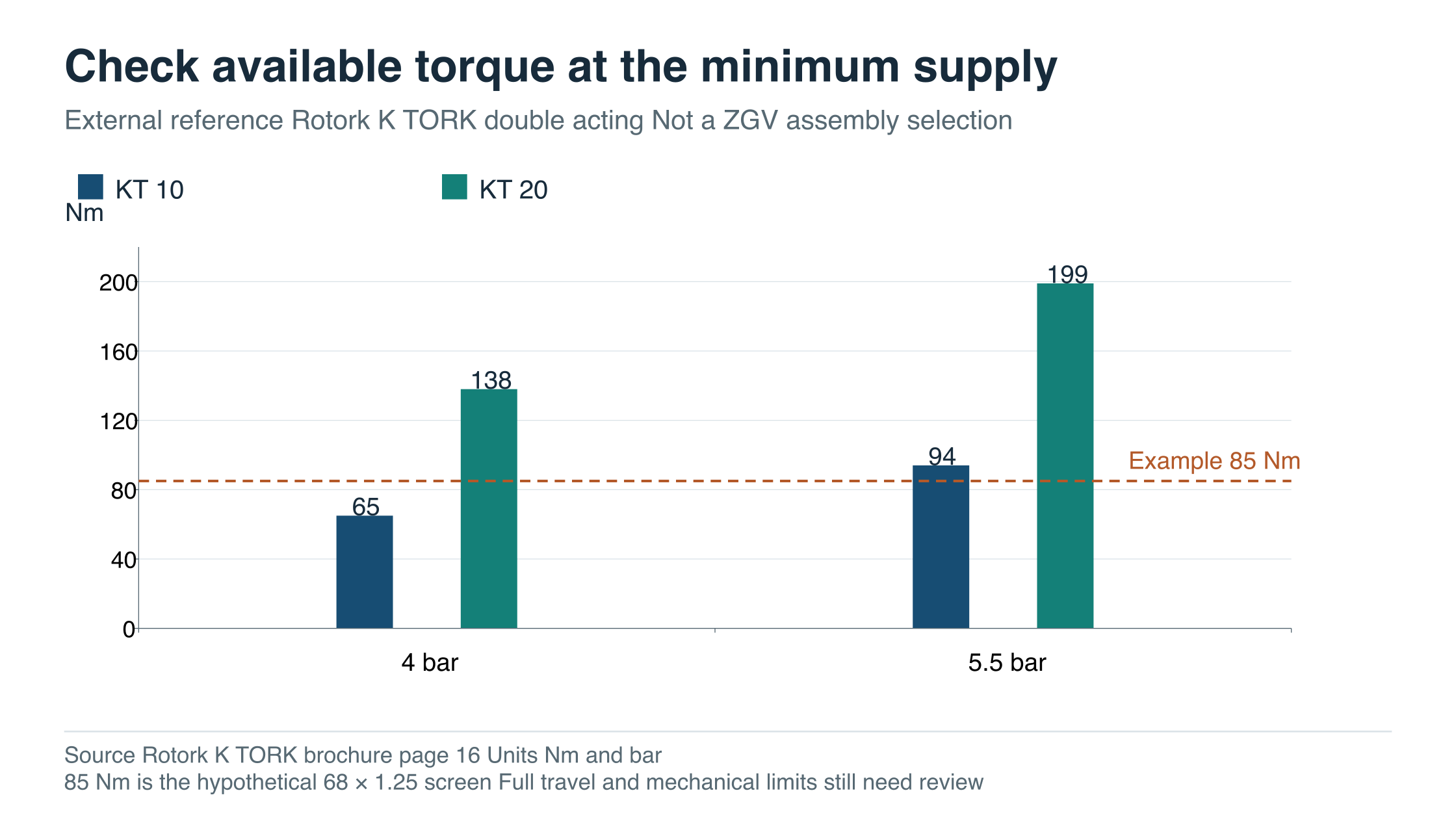
Rotork’s K-TORK brochure publishes these selected double-acting torque outputs. They are external manufacturer data used here to explain a sizing check.
| Published double-acting model | Output at 4 bar Nm | Output at 5.5 bar Nm |
|---|---|---|
| KT-10 | 65 | 94 |
| KT-20 | 138 | 199 |
Scroll the table horizontally on a small screen.
Source: Rotork K-TORK brochure, Performance Data, page 16. Values apply to the models and table conditions stated by Rotork. They do not establish a ZGV actuator selection, a supply relationship or mechanical compatibility.
Now assume a hypothetical valve requirement of 68 Nm at a critical point and an illustrative project factor of 1.25. The resulting screening requirement is:
68 Nm × 1.25 = 85 Nm
The 1.25 factor is an assumption in this example, not a universal sizing recommendation. The project and valve supplier need to define the actual allowances.
At 5.5 bar, the KT-10 table value of 94 Nm exceeds the illustrative 85 Nm requirement. At 4 bar, its 65 Nm value falls below it. Reading only the higher-pressure column would therefore miss the lower-supply shortfall in this example.
The KT-20 value at 4 bar clears that single numerical screen. It still does not approve the complete selection: the remaining travel, valve load limits, connections, speed and failure requirements must also be satisfied.
Swipe or scroll horizontally to see the full diagram.
Define the pressure at the actuator while it is moving
The compressor outlet pressure is not necessarily the pressure available at the actuator inlet during a demanded stroke. Filters, regulators, solenoid valves, tubing and other users on the supply can affect the pressure and flow delivered to the package.
Give the supplier the minimum available dynamic supply pressure at the relevant connection, together with the maximum supply and required action time. That lets the supplier identify the correct sizing condition and select the associated air components.
A static gauge reading taken with nothing moving is useful site information, but it is not a complete demonstration of the demanded stroke. For a package with a specified fast action, the supply flow and the restrictions in the accessory circuit deserve attention as well as pressure.
Keep supply-pressure units clear. The process line pressure, the actuator air supply and the differential pressure across the valve are three separate inputs. A repeated number in different fields does not make them interchangeable.
Compare the whole movement
The valve may need different torque to break away from its seat, continue moving and complete closure. Required loads can also differ between opening and closing. Obtain the manufacturer’s load information for the actual valve trim and conditions.
An actuator likewise has an output characteristic. A single peak torque is insufficient when the critical valve demand occurs elsewhere in the stroke. The review should compare available output and required load at the relevant positions in both directions, including the agreed allowances.
Spring-return sizing adds another comparison. Both the powered stroke and the spring stroke must meet their respective demands. The spring arrangement, preload and supply basis need to be identified. A spring-return table may present matched configurations for different supply conditions; those columns should not automatically be plotted as the pressure-decay performance of one unchanged assembly.
Also check the maximum supply condition against the valve’s permissible stem torque or thrust and the coupling and bracket limits. The higher output that resolves a low-supply shortfall may exceed a mechanical limit elsewhere in the package. Size the actuator and confirm the complete drive train together.
Extend the worked example to three load points
Continuing the same hypothetical example, assume 68 Nm at breakaway, 42 Nm while running and 60 Nm at final seating. Apply the same illustrative factor of 1.25 to each point.
| Assumed load point | Valve requirement Nm | Illustrative screened requirement Nm |
|---|---|---|
| Breakaway | 68 | 85 |
| Running | 42 | 52.5 |
| Final seating | 60 | 75 |
Scroll the table horizontally on a small screen.
The three valve-load values are assumed for this worked example; they are not ZGV torque data. The published KT-10 value of 65 Nm at 4 bar falls below the assumed breakaway and seating requirements after the factor is applied. It is also below the bare 68 Nm breakaway assumption, so the shortfall in that example is not solely caused by the allowance.
The table explains the review method, rather than replacing a full load curve. Actual load and output may need checking at other positions and conditions. The final selection also needs the valve’s maximum permissible stem load and the coupling and bracket limits, particularly at the maximum available supply.
Write the failure action for each event
“Fail safe” needs a defined event and a required final state. Loss of air, electrical power and control signal may affect different components. The system design must establish what the valve is expected to do in each case.
| Event to specify | Confirmation required from the package supplier |
|---|---|
| Loss of pneumatic supply | Required valve position, available stored energy and ability to complete the movement |
| Loss of electrical power | Solenoid or electric-drive response and resulting valve action |
| Loss of control signal | Controller or positioner response and the agreed valve state |
| Return of supply or signal | Defined restart behaviour and any required reset |
Scroll the table horizontally on a small screen.
A double-acting pneumatic label alone does not establish a reliable last-position function or a particular failure action. The accessory circuit and any stored-energy arrangement matter. A spring-return label likewise needs a confirmed direction, load basis and complete package configuration.
Electric operation can also be supplied with an engineered stored-energy failure action. Rotork’s RCE-SR electro-hydraulic range, for example, describes spring-open or spring-close arrangements for duties where pneumatic supply is unavailable or unsuitable. This shows why failure action should be specified directly rather than inferred solely from the energy source. Rotork RCE-SR description
Treat ISO 5211 as interface information
ISO 5211 addresses part-turn actuator attachment dimensions, driving components and reference interface torque values. Its public scope also identifies a boundary: attachment of an intermediate support to the valve is outside its scope. The ISO page lists a 2026 edition. ISO 5211 official scope
A matching attachment designation helps define the interface. It does not, by itself, verify the complete bracket, coupling engagement, shaft shape, assembly alignment or load capacity. The supplier should provide the relevant drawings and confirm the assembled load path.
Part-turn and multi-turn duties also need to stay separate. A ball or butterfly valve may require part-turn movement, while a rising-stem gate assembly may require a different combination of torque, thrust, travel and turns. A part-turn torque table cannot size that linear movement by itself.
ZGV’s pneumatic butterfly valve entry, electric butterfly valve entry and electric flat gate entry identify different offered product categories. Their public presence does not establish a common actuator interface or a complete sizing curve for every configuration.
Ask for a package calculation with identifiable inputs
The calculation package should identify the valve size and trim, service pressure and temperature, operating differential pressure, required loads, allowances, available actuator output and mechanical limits. Supply pressure, spring configuration and accessory circuit should be identifiable wherever they affect the result.
Action time and operating frequency belong beside that calculation. An actuator suited to occasional isolation may need a different assessment for frequent modulation. Electrical duty, pneumatic flow capacity, ambient conditions and environmental protection should match the specified use.
Confirm the assembled valve and operator, including every supplied gearbox, bracket, coupling, solenoid, positioner and indicator. For an automated ZGV enquiry, send the minimum dynamic air supply, maximum supply, required failure states and process duty. Request a package calculation and assembly drawing using those same inputs.
Send the valve RFQ worksheet with the minimum dynamic supply pressure, required action times and failure-action schedule. Request a sizing calculation for the complete package. You can send the assembled valve enquiry to ZGV.