
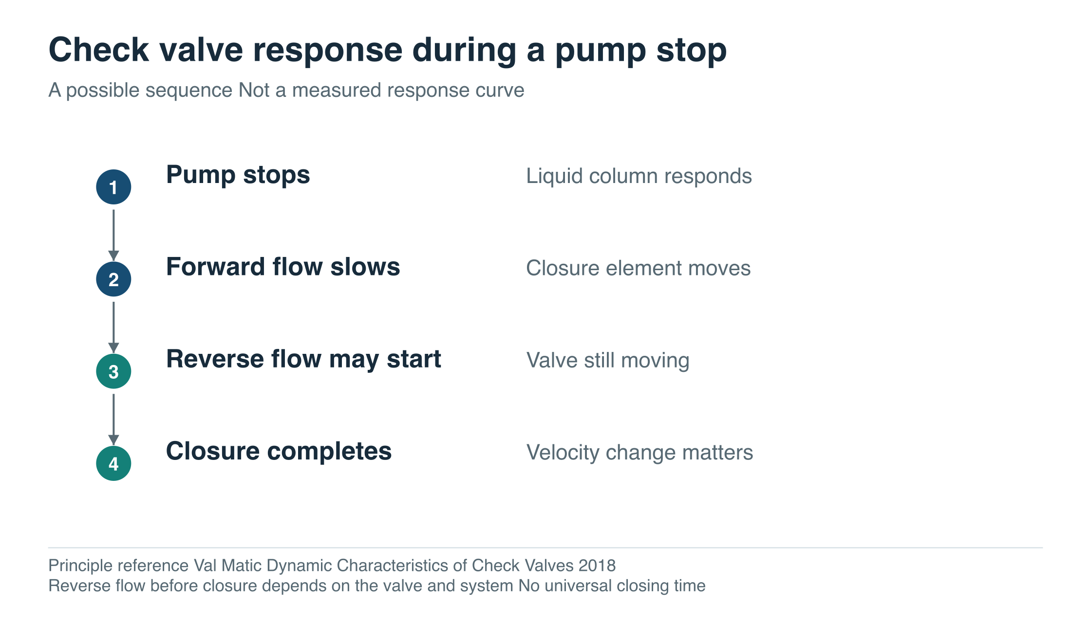
After a pump stops, the liquid column and the check valve continue to respond to changing forces. Forward flow decelerates while the closure element moves toward its seat. The relative timing matters.
If appreciable reverse flow develops before closure, stopping that flow can create a pressure surge. A short, light valve may be attractive to install, but its length and weight do not tell the buyer how it will behave at that moment.
For pump discharge service, compare steady flow, closing response and installation as separate requirements. Each needs its own evidence.
Follow the shutdown sequence
A check valve responds to the fluid rather than a normal external command. Its movement depends on the forces acting on its closure element. Swing, lift and spring-assisted arrangements therefore need to be assessed in the context of flow, orientation and the particular design. Spirax Sarco check valve principles
A check valve’s automatic reverse-flow function does not replace the project’s required isolation arrangements.
During a pump trip, the liquid column does not necessarily stop when the motor loses power. Pump inertia, the piping profile, static head and other connected equipment influence the change in flow. A valve may start closing while forward flow remains, or it may still be moving after flow has reversed.
Val-Matic’s dynamic check valve paper relates the system’s flow deceleration to the reverse velocity reached before closure. Its test results concern the specified test valves and conditions; they are not ZGV performance curves. The useful procurement lesson is to request response evidence for the offered design, size and installation. Dynamic Characteristics of Check Valves, 2018
A claim of “non-slam” should therefore lead to a discussion of the applicable duty. It should not end that discussion. The name alone does not describe the pump trip, the fluid deceleration or the valve’s closure behaviour in the proposed installation.
Swipe or scroll horizontally to see the full diagram.
Compactness is useful but answers a different question
ZGV publishes the following selected geometry entries for a Class 150 swing check valve and a compact check valve listed on its site as “butterfly swing check valve Class150/300.”
| Published entry | Size | Listed L mm | Listed weight kg |
|---|---|---|---|
| Swing check, RF | NPS 2 | 203 | 20 |
| Compact check entry | DN 50 / 2 inch row | 43 | 1.5 |
| Swing check, RF | NPS 4 | 292 | 55 |
| Compact check entry | DN 100 / 4 inch row | 64 | 5.7 |
Scroll the table horizontally on a small screen.
Sources: swing check product 2553 and compact check product 2563. The second page presents one dimension table under a Class 150/300 heading. Confirm the selected class, construction and connection drawing rather than assuming those details from this extract.
The compact entry plainly offers a different installation envelope. These figures can help a buyer identify where layout work is required. They do not establish an equivalent pressure rating, leakage result or dynamic response, and they do not mean the compact option can replace a flanged swing check without changes to the installation.
For a wafer-style installation, check the closure element’s full travel against the nearby pipe and equipment clearances. For a full-body swing check, access to the cover and internals may drive the maintenance layout. The approved drawing should show the proposed arrangement, including the parts that move or must be removed.
Check the lowest flow as well as the design flow
A pump can spend substantial time below its maximum flow. In a multiple-pump system, the operating points may differ depending on which pumps are running. The check valve needs to be evaluated at those actual points.
Opening pressure is one item; stable operation over the required flow range is another. A valve that starts to open at a low differential pressure may still require a higher flow to hold its closure element in a stable position. Ask for the minimum stable flow or velocity for the proposed size, where applicable, and the pressure loss at the stated operating points.
An oversized valve selected only to match a pipe diameter can therefore deserve further review. Selecting a smaller valve also changes pressure loss and may require transitions. Neither change should be accepted without evaluating the full duty. Val-Matic design and selection discussion
ZGV also lists flanged forged lift check valves. Their existence provides another design option to discuss; it does not establish that a particular lift construction suits vertical mounting, pulsating service or a given minimum flow. Those points belong in the technical confirmation.
A small reverse velocity can still matter
An explanatory calculation helps show why reverse velocity is worth asking about. For a simple rapid change in liquid velocity, the Joukowsky relationship is:
Pressure change Δp = liquid density ρ × wave speed a × velocity change Δv
For this example only, assume water density 1,000 kg/m³ and wave speed 1,000 m/s. Assume the velocity change is rapid enough for this simplified relationship to apply.
| Assumed reverse velocity brought to rest | Calculated pressure-change magnitude |
|---|---|
| 0.2 m/s | 200,000 Pa = 2 bar |
| 0.8 m/s | 800,000 Pa = 8 bar |
Scroll the table horizontally on a small screen.
These are hypothetical sensitivity calculations, not measured ZGV results and not predictions for a particular pump station. They omit the complete boundary conditions, wave reflections, possible liquid-column separation and other effects of a real transient. They should not be used to size surge-control equipment or approve a valve.
KSB’s surge-pressure guide explains the equation and the limits of using simple estimates for a system analysis. The calculation here changes the assumed reverse velocity to show its influence while keeping density and wave speed fixed. KSB Surge Pressure, pages 11–16
For procurement, the result supports a specific request: supply the valve response data that the system analyst needs. It does not support a blanket rule that every check valve must close as fast as possible. The required closing behaviour has to fit the system.
Specify the orientation and the transient
“Vertical installation” is incomplete without the flow direction. A horizontal test result may not represent an upward or downward installation, particularly where gravity contributes to closure. The exact hinge, spring and closure arrangement also matters; do not infer these details from a broad family name.
Include the pump trip and normal stop sequence where the duty involves a significant transient. A controlled stop and a power failure may present different conditions. If the line includes a surge vessel, long rising main, multiple pumps or changing boundary conditions, those features belong in the information passed to the system analyst and valve supplier.
Also describe solids and deposits. A closure mechanism that needs a clear movement path must be reviewed for the actual fluid. Reducing surge tendency does not remove the need to assess clogging, wear and access for maintenance.
Read a supplier reply against the operating stage
If a proposal gives a low opening pressure but no information about the minimum operating flow, it has answered the initial-opening question. The buyer still needs to know how the closure element behaves during prolonged low-flow operation.
If it gives pressure-loss data at normal flow but no response information for the pump trip, it supports the steady-state comparison. It leaves the shutdown comparison open. A smaller steady loss cannot be used to fill in that missing dynamic response.
If it includes a dynamic curve, check its size, orientation and configuration before passing it to the system analyst. A curve for another arrangement may explain the method while remaining unsuitable as numerical input for the proposed valve. Keeping each piece of evidence attached to its operating stage makes those gaps visible without dismissing useful data.
Information that makes the supplier’s reply useful
| Information from the project | What to obtain in the reply |
|---|---|
| Minimum, normal and maximum operating flow | Pressure-loss data and any minimum stable operating requirement |
| Pipe size, material and installation orientation | Approved connection and movement-clearance drawing |
| Pump stop and trip conditions | Relevant dynamic response data and its size/orientation limits |
| Fluid and solids description | Material, closure and seat suitability for the stated medium |
| Required reverse-flow containment | Defined seat-leakage test and acceptance requirement |
| Maintenance access and outage constraints | Accessible components, removal space and proposed spare parts |
Scroll the table horizontally on a small screen.
Approve the fit, steady-flow behaviour and shutdown response as separate items. This keeps a useful space saving from obscuring an unresolved pump-trip requirement. For a ZGV enquiry, provide the operating range and system information alongside the chosen swing, lift or compact check catalogue reference. Ask for the remaining evidence before treating any option as a duty match.
Use the valve RFQ worksheet for the base enquiry, and attach the operating-flow range, installation orientation and pump-stop scenario for the response review. You can send the check valve enquiry to ZGV.