
A complete replacement connection schedule gives buyers a clear way to compare RF and RTJ valve offers. Review the existing mating flanges and the proposed sealing arrangement alongside size, class and installation length.
RF and RTJ describe different flange-facing arrangements. Approve the mating facing, gasket system, dimensions, bolting and complete valve envelope together. Similar pressure capability does not establish mechanical interchangeability.
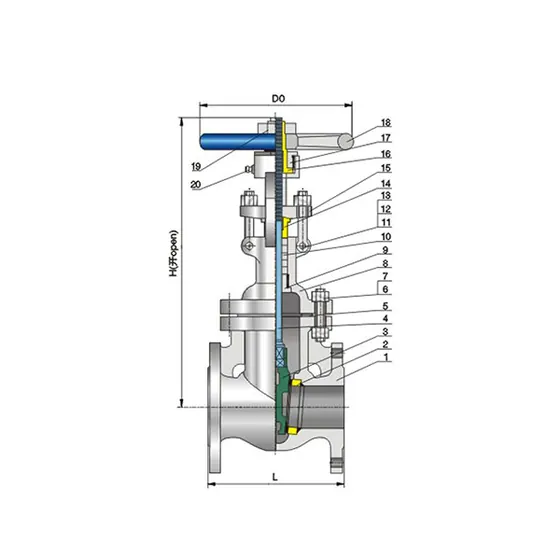
ZGV publishes gate- and globe-valve dimensions that let replacement buyers compare the proposed valve before ordering. Combine those catalogue references with the actual mating-flange details and available space to request a clear connection drawing and quotation.
Read the facing as part of the connection
RF means raised face. RTJ means ring-type joint, using a machined groove and the specified ring joint system. Those descriptions identify different sealing arrangements; they are not alternative gasket names for an otherwise unspecified connection.
The governing flange standard, size, pressure class, material and facing details should appear on the enquiry and approved drawing. The ASME B16.5 publisher description identifies the flange and flanged-fitting framework. Use the required edition and component details for actual dimensions and acceptance.
For an existing line, obtain the original drawing where available and verify the actual installation. A nameplate may identify the valve without recording every mating-flange detail. Photographs help explain the layout but cannot reliably establish groove dimensions, facing condition or the full pressure-rating basis.
Identify the seal before comparing dimensions
An RF joint compresses its specified gasket across the raised sealing faces. An RTJ joint locates its specified metal ring in matching grooves. The ring profile/number, material and groove details therefore belong together in the connection schedule.
Record an apparent RF-to-RTJ mismatch as a facing deviation. Confirm the mating interface and any engineered change before ordering; choosing a gasket by outside diameter or matching bolt holes leaves the sealing geometry unresolved.
Make a connection schedule before ordering
| Field | Information to record |
|---|---|
| Mating standard | Standard and edition required by the project |
| Size designation | NPS/DN and actual relevant mating dimensions |
| Rating | Class/PN, material and applicable pressure-temperature basis |
| Facing | RF, RTJ or other specified arrangement, with required detail |
| Gasket system | Type, size, material and relevant specification |
| Bolting | Grades, dimensions and approved assembly requirements |
| Installation length | Applicable face-to-face/end-to-end dimension and reference surfaces |
| Bore and pipe | Actual inside dimensions, schedule and interference checks |
Record both ends. A transition or special installation can have different requirements at each side. A single connection field can hide that difference.
Length and facing are separate approval items
ZGV's Class 150 gate valve 2524 and globe valve 2541 publish separate RF and RTJ dimensions. The NPS 4 rows make the facing-dependent length difference visible:
| Published ZGV catalogue configuration | NPS | Class | RF length | RTJ length |
|---|---|---|---|---|
| Gate valve 2524 | 4 | 150 | 229 mm | 242 mm |
| Globe valve 2541 | 4 | 150 | 292 mm | 305 mm |
These values come from the specific catalogue rows linked above. Compare the actual offered end pattern and drawing with the verified site gap; include the operator and maintenance envelope separately.
The ASME B16.10 scope addresses valve installation dimensions for specified configurations. A buyer still needs the correct table and offered drawing. Shared size and class do not make every valve type or end pattern interchangeable.
In a replacement job, matching one dimension cannot compensate for the wrong facing. Matching the facing cannot compensate for the wrong installed length. Keep each requirement in its own row rather than collapse them into fits existing flanges.
Do not use bolt-hole alignment as the acceptance test
Two connections may appear to bolt together while the sealing surfaces, gasket arrangement or rating basis remain unsuitable. Bolt-hole alignment is a geometric observation, not evidence of a qualified joint.
Likewise, do not force pipework into place to resolve a length or alignment discrepancy. The installation design should address pipe loads, supports, tolerances and the approved assembly method. A valve is not an alignment tool.
A supplier proposing an adapter or changed connection should identify it as a design change. Review the additional joints, space, loads, materials and pressure-temperature limits. A workaround that makes the bolts reach has not necessarily preserved the original system design.
A fictional replacement review
Assume a fictional request says “NPS 4, Class 150, replace existing valve.” The first quotation offers RF ends. Site photographs suggest another facing, while the original documentation is incomplete.
| Step | Decision that can be made |
|---|---|
| Catalogue review | Identify the proposed RF configuration and its published dimensions |
| Site/document verification | Establish the actual mating arrangement and required envelope |
| Supplier clarification | Obtain a revised drawing or explicit confirmation against verified data |
| Engineering disposition | Approve any changed joint, adapter or pipework scope |
| Order release | Freeze the accepted connection schedule and drawing revision |
At the first step, the buyer has an offer to investigate. There is not yet enough evidence to call it a direct replacement.
Include operating and maintenance space
A correctly matched flange still leaves the operator, stem travel and maintenance access to review. Rising stems need the open envelope. Quarter-turn handles and discs need their movement space. Gearboxes, electric actuators, cables and insulation can create interference absent from a bare-valve drawing.
Have the final drawing mark the relevant reference points and all required envelopes. The gate/globe replacement guide gives a dimensional example; use the actual offered connection and operator for approval.
Send ZGV both sides of the interface
For a ZGV quotation, identify the required valve function and attach the mating-flange details, verified space and piping specification. Ask for the exact end pattern and a connection drawing, with any deviation marked before purchase.
Distinguish the catalogue valve length from the actual site gap and the approved joint assembly allowances. Gaskets, tolerance and the installation method need the correct project treatment. Do not add a guessed allowance to make a catalogue row appear to fit.
Submit the replacement connection schedule with the product reference. The useful outcome is an approved joint and assembly that match the installation, supported by a drawing the site team can use.
ZGV VALVE · Zhejiang Zhonggong Valve Group Co., Ltd. · Quality and certification records
Download the ZGV valve RFQ template and share your service conditions, quantities and required documents with ZGV.