
Replacing an NPS 4 Class 150 gate valve with a globe valve can require more pipe length even when the flanges appear to match. In ZGV’s published raised-face (RF) configurations, the listed lengths are 229 mm for the gate valve and 292 mm for the globe valve—a difference of 63 mm.
That is an installation issue. The first selection question is still the job: will the valve normally isolate the line, or must it regulate flow between fully open and fully closed? Gate and globe valves move their closure elements in a straight line, but their flow paths and intended duties differ.
Start with how the valve will be used
A gate valve lifts its gate out of the flow path and is normally selected for isolation. A globe valve moves its disc relative to a seat in a flow path that changes direction. The latter arrangement can support regulation, while also introducing a different flow resistance. Spirax Sarco explains this difference in its linear-movement valve tutorial. Gate and globe valve operating principles
For an isolating line valve that will spend most of its life fully open, the buyer should examine open-valve pressure loss, shutoff conditions and the ability to operate when required. Using a gate valve as an improvised throttling device changes that duty and needs an explicit design review rather than an assumption based on the handwheel’s intermediate positions.
For a line that needs manual adjustment, a globe design may be a candidate. The required flow, pressure drop and trim must still be checked. A standard handwheel globe valve is not automatically an adequately sized automatic control valve, nor does a catalogue category establish a stable operating range.
The deciding requirement should be written into the enquiry. “NPS 4 valve for a steam line” is incomplete. “Isolation, normally fully open, required to close against the stated differential pressure” gives the supplier a much clearer task.
The same size and class do not mean the same envelope
The table below compares selected Class 150 RF entries from ZGV’s rising-stem gate and globe valve tables.
| Size and valve | RF length mm | H open mm | RF weight kg |
|---|---|---|---|
| NPS 2 gate | 178 | 409 | 20 |
| NPS 2 globe | 203 | 373 | 22 |
| NPS 4 gate | 229 | 612 | 55 |
| NPS 4 globe | 292 | 515 | 64 |
| NPS 6 gate | 267 | 806 | 85 |
| NPS 6 globe | 406 | 567 | 105 |
Scroll the table horizontally on a small screen.
Sources: ZGV Class 150 gate valve, product 2524 and Class 150 globe valve, product 2541. In both source diagrams, H open is measured from the pipe centreline to the indicated upper limit in the open condition. Final assembly and maintenance clearances require the approved drawing; weights are catalogue values, not a lifting plan.
The NPS 4 globe entry is longer and heavier in this comparison, while the gate entry has the larger H open. At NPS 6, the listed RF length difference grows to 139 mm. There is no single “smaller valve” across all dimensions: the available axial space and overhead space may favour different configurations.
ASME B16.10 addresses valve installation dimensions for specified combinations of material, type, size, class and end connection. Its scope should not be simplified into a promise that all valves sharing a size and class are directly interchangeable. ASME B16.10 official description
Review three spaces in a replacement job
Space between the pipe ends. Measure the existing installation and identify the actual facing and end connection. In the NPS 4 example, a 229 mm gap does not accommodate a 292 mm catalogue length without changes. Do not solve a dimensional mismatch by forcing the pipework to meet the valve.
Space during operation. A rising stem needs its full movement envelope. The catalogue H open is useful, but it needs a defined reference point and the proposed operator arrangement. An insulated line, cable tray or platform above the handwheel may become the limiting obstruction.
Space for maintenance. The room needed to remove a bonnet, stem or internal assembly can exceed the normal operating envelope. That extra space is not established by H open alone. Ask for the maintenance removal requirement when the valve will sit beneath fixed steelwork or other equipment.
The distinction is easy to miss on a model that shows the valve only in its closed position. For a congested skid, have the supplier mark both operating and maintenance envelopes on the assembly drawing before the layout is fixed.
Check both directions in the same layout
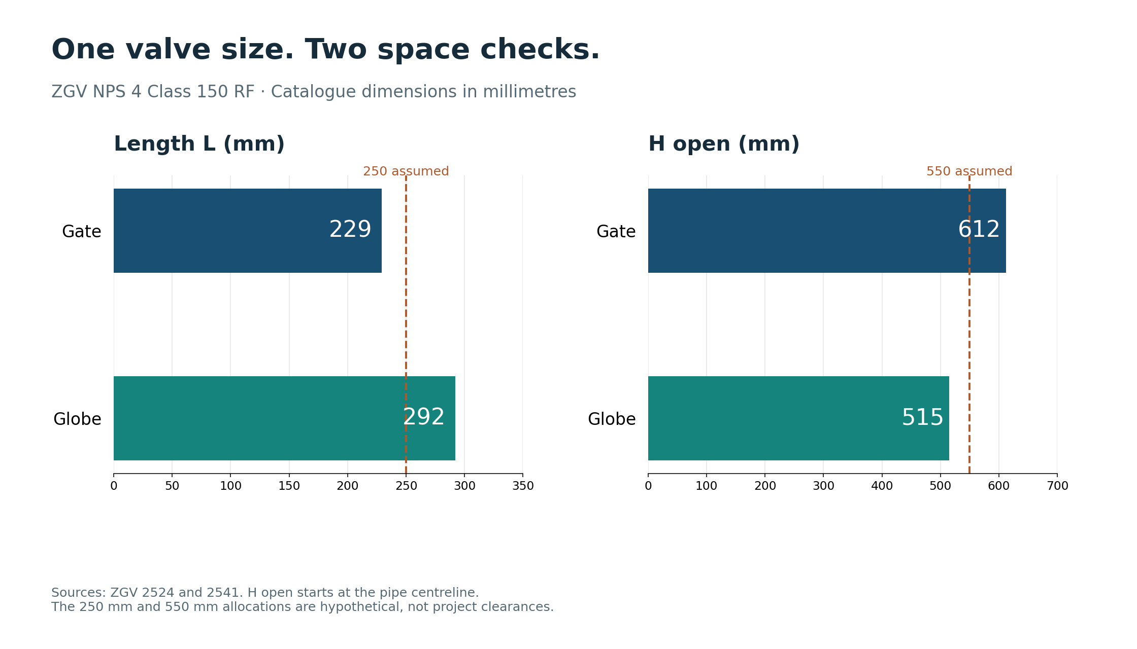
Take a hypothetical NPS 4 layout with 250 mm allocated along the pipe and 550 mm of height allocated above the pipe centreline. Use the source L and H-open reference points for this first screen. Connection details, installation allowances and maintenance removal space still need the actual project drawing.
The gate entry’s 229 mm length falls inside the axial allocation by 21 mm, but its 612 mm H open exceeds the height allocation by 62 mm. The globe entry’s 515 mm H open falls inside the height allocation by 35 mm, but its 292 mm length exceeds the axial allocation by 42 mm.
Neither entry clears both dimensional screens in that assumed space. This is the practical reason to compare the envelope in more than one direction. The figures do not establish installation allowance, gasket space or maintenance clearance; those require the actual drawing and connection details.
Swipe or scroll horizontally to see the full diagram.
Compare pressure loss at the required flow
The flow path provides a reason to expect different hydraulic behaviour, but it does not provide a numerical pressure-loss comparison. Obtain Cv or Kv data for the offered sizes and trims, then compare at the same fluid conditions and flow rate.
For isolation duty, check the loss with the valve fully open. For regulation duty, check the required operating positions as well as the extremes. A valve that can pass the maximum flow may still be a poor choice if the normal duty requires operation in an unsuitable part of its travel.
Where the fluid can change phase or the pressure reduction is substantial, the sizing review needs to address that condition. A simple water-flow comparison cannot establish performance for steam, flashing or cavitating liquid service.
The extra pressure loss may be a deliberate part of regulation. It may be an avoidable operating cost in an otherwise unrestricted isolation line. The duty determines how the loss should be assessed; a general statement that one valve is “more efficient” misses that distinction.
Material schedules do not erase design differences
The selected ZGV gate and globe tables both list a WCB body and an A105 + 13Cr seat ring. The gate entry lists a WCB + 13Cr wedge, while the globe entry lists an A105 + 13Cr disc. Gate component table and globe component table
These shared material descriptions help identify the offers, but they do not make the flow path, closing load or installation dimensions equivalent. A material substitution review and a valve-type substitution review are separate pieces of work.
The closing differential pressure is particularly useful information. A normal line pressure without the downstream condition does not tell the supplier what load the closure must work against. State whether the valve must open or close with one side depressurised, and identify any required operating sequence.
Turn a broad comparison into a purchase decision
| If the job requires | The proposal should demonstrate |
|---|---|
| Routine isolation with low open-valve loss | Suitable isolation design, configuration-specific flow data and required shutoff |
| Manual regulation | Appropriate disc/trim, acceptable operating range and conditions at the intended positions |
| Replacement without pipe modifications | Matching approved length, end details and complete envelope |
| Installation under fixed overhead equipment | Full open position and maintenance removal clearances |
| Operation against the specified pressure difference | Closing/opening load basis and suitable manual or powered operator |
Scroll the table horizontally on a small screen.
For a replacement enquiry, attach the existing drawing or measured installation and state whether the job is isolation or regulation. Use ZGV gate product 2524 or globe product 2541 as the catalogue reference. The reply should mark dimensional deviations, show the full movement and maintenance envelopes, and identify the flow and operating-load basis for the proposed duty.
Send the valve RFQ worksheet with the existing layout and the required operating and maintenance envelopes. Mark the actual end connections and dimensional reference points. You can send the replacement enquiry to ZGV.