
Reviewing trapped liquid during ball-valve selection brings the line-isolation duty and cavity-pressure arrangement into the same discussion. A closed valve can retain liquid in its body cavity; a later temperature rise makes the relief path a useful procurement question.
Cavity pressure relief addresses a trapped volume in the valve. The proposed mechanism, discharge destination and pressure directions must be identified. It does not automatically provide the system's required overpressure protection.
ZGV's floating and trunnion ball-valve ranges provide identifiable configurations for a project enquiry. Bring the trapped-volume sketch and pressure cases to the discussion so the proposed drawing, seat directions and relief scope can be reviewed as one package.
Find the trapped volume first
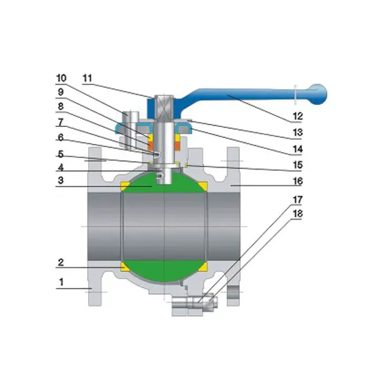
Start with a sectional drawing of the offered valve in its relevant positions. Mark spaces that can retain fluid after closure, then identify how those spaces connect to the line or to a separate relief system. A general flow arrow is not a complete cavity drawing.
The operating sequence matters. A valve closed after carrying cold liquid may later warm toward ambient temperature. A heated line can expose a retained volume to a different temperature from the upstream process. Adjacent isolation valves can also trap a section of pipe outside the ball valve. That pipe section and the valve cavity are different volumes requiring their own design assessment.
For procurement, describe the fluid, credible temperature change, pressure cases and surrounding isolation arrangement. Do not estimate an allowable trapped pressure from the catalogue class number alone.
Why a small trapped volume still matters
The relevant question is whether the retained liquid can expand into an available volume or escape through an engineered route as it warms. Even a small cavity needs that review. Its initial pressure does not set a dependable upper limit after heating, and a pressure gauge outside the isolated cavity may not show the cavity pressure.
Follow the pressure path on paper: retained cavity → relieving component or passage → receiving side or discharge system. If the route ends at another isolated pocket, the review has found another trapped volume rather than a completed solution. Identify both volumes and their protection in the design documents.
Understand the proposed relief route
Several design approaches are used in the industry. Use the table to define the function to discuss, then identify the mechanism and scope in the offered ZGV configuration.
| Proposed approach | What the buyer needs to establish |
|---|---|
| Self-relieving seat | Conditions under which cavity pressure can discharge to a line side |
| Dedicated internal passage | Which side is connected and how that affects sealing direction |
| External relief arrangement | Set basis, capacity basis, destination, isolation control and required protection |
| Engineered integral device | Specific design, response basis, limitations and applicable qualification |
Habonim's cryogenic valve discussion illustrates why a relief passage and bidirectional isolation cannot be evaluated independently. Its proprietary integral device is one manufacturer's solution. It is not a feature that can be inferred for ZGV from the same broad valve family name.
A relief route is only useful if its destination remains appropriate in the conditions being reviewed. Ask what happens when the pressure at that destination rises, flow reverses or a nearby valve is closed. Those conditions should be part of the technical response.
Separate three different pressure functions
Line isolation controls flow through the main passage. Cavity pressure management addresses the volume retained inside the valve. System overpressure protection addresses equipment or piping under the governing design requirements.
A component can contribute to more than one function, but the roles are not interchangeable. A cavity that relieves into an already pressurised pipe has not necessarily protected the rest of the plant. Conversely, a system relief valve may not protect an isolated pocket unless the engineered arrangement provides an effective connection.
Spirax Sarco's safety-valve tutorial explains the separate system protection function. It should not be used to size a ball-valve relief arrangement by analogy. The application, protection basis and responsible designer need to be identified.
A pressure-direction worksheet
Consider a hypothetical installation in which a liquid service can flow in either direction and both pipe ends may be isolated elsewhere. The following worksheet makes the unresolved questions explicit.
| Operating condition | Supplier/design-team response required |
|---|---|
| Valve closed after liquid flow | Identify the retained cavity and initial pressure |
| Retained liquid warms | State the proposed cavity-protection mechanism and design basis |
| Normal upstream side becomes lower pressure | Explain whether relief and required isolation remain available |
| Both neighbouring line valves close | Review the cavity and separately trapped pipe sections |
| Relief destination pressure rises | Explain the resulting limits and required additional measures |
| Valve is serviced or transported | Define approved depressurisation and preservation requirements |
The worksheet does not establish that a particular valve is suitable. It supplies cases that the offered design must answer before approval.
What to request from ZGV
ZGV's 2511 floating and 2514 trunnion mounted entries provide ball-valve configurations, original drawings and material tables for a focused enquiry. Identify the selected trim and seat arrangement when discussing its cavity-relief mechanism.
Ask for a configuration-specific sectional drawing, the seat-pressure directions, the actual relief path and any marking or installation restrictions. If the offer relies on external equipment, identify whether that equipment is included and who designs and approves it. The quotation should also make exclusions clear so a required protective component is not lost between packages.
Where the project calls for a test or qualification, specify what it must demonstrate. A routine shell test at room temperature does not, by itself, describe relief behaviour under all relevant conditions. The test procedure and the accepted design evidence answer different parts of the review.
Read vague statements as open questions
“Automatic relief” needs a mechanism and destination. “Bidirectional” needs the pressure directions and function it describes. “Suitable for liquid” needs the actual fluid and operating sequence. None of these phrases is necessarily wrong; each is incomplete until attached to a defined offered build.
Keep the requirement, supplier response and engineering disposition together. If a route changes to preserve a required isolation function, review the updated relief arrangement as well. That prevents an improvement to one function from leaving another unexamined.
Give every required relief item an owner in the supply boundary. If the valve supplier provides a connection but another contractor supplies the protective device and discharge piping, record both scopes. An unassigned connection is not a completed protection arrangement.
Send the trapped-volume and pressure-direction information with the chosen catalogue reference. Request the drawing and scope needed to assess the complete arrangement before the order is approved.
ZGV VALVE · Zhejiang Zhonggong Valve Group Co., Ltd. · Quality and certification records
Download the ZGV valve RFQ template and share your service conditions, quantities and required documents with ZGV.