
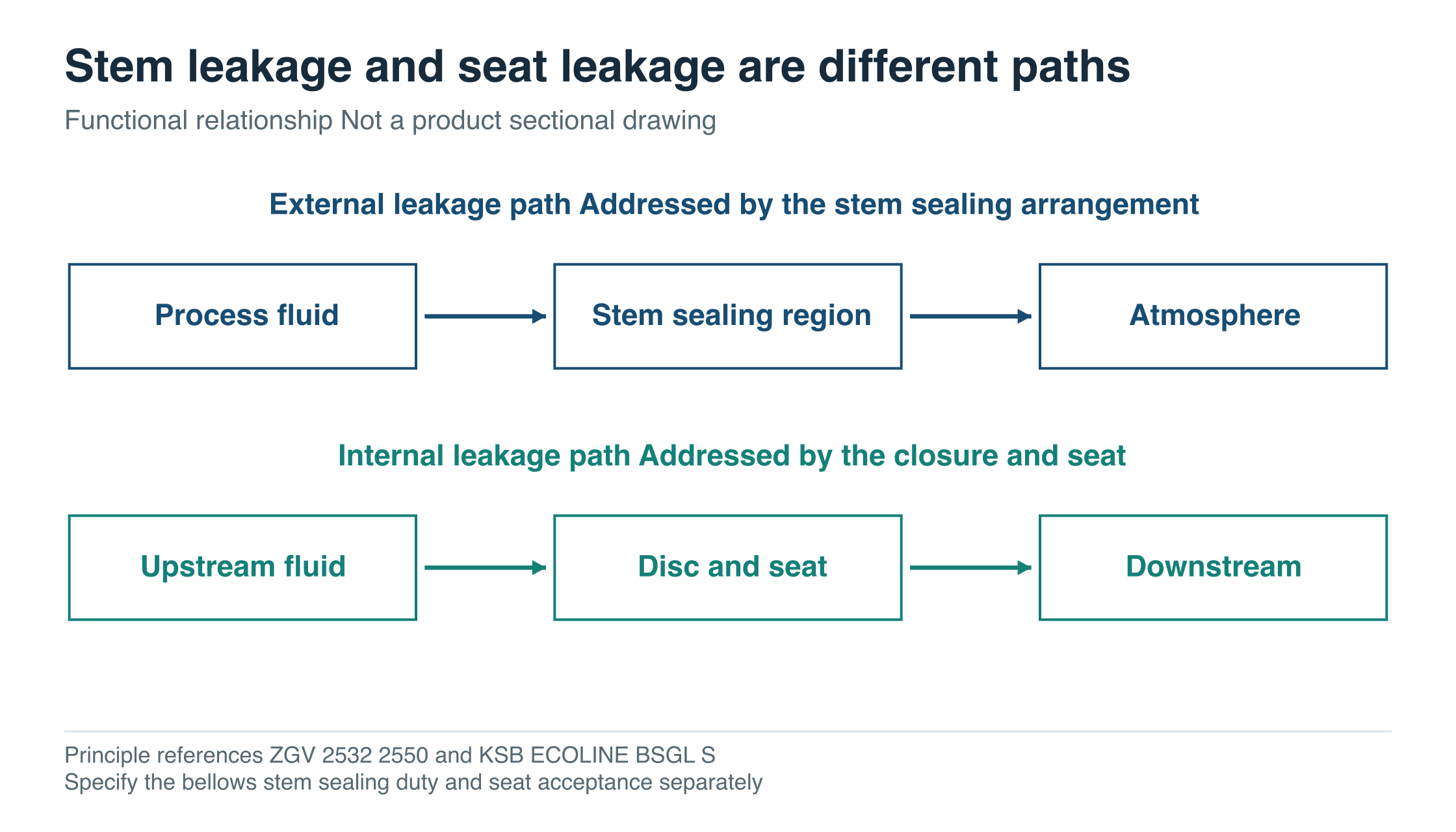
Steam escaping around a valve stem and fluid passing through a closed valve seat are different problems. A bellows stem seal addresses the first path. The seat and closure element still determine the second.
That distinction is the starting point for specifying a bellows sealed valve. The buyer then needs to understand the bellows material, its movement, the pressure-temperature conditions and the evidence behind any expected cycle life.
Separate the two sealing duties
In a typical bellows sealed globe or gate valve, the bellows forms a flexible barrier around the moving stem. It accommodates the required stem movement while separating the process fluid from the stem sealing region above it. Backup packing may provide an additional barrier in the arrangement.
KSB’s ECOLINE BSGL-S description explicitly identifies a primary bellows seal and backup gland packing. That is a useful example of the two-barrier concept; the particular materials and product limits remain model-specific. KSB bellows sealed globe valve description
Inside the flow path, a separate disc or gate closes against its seat. A stem sealing claim does not specify how much leakage is permitted across that seat. Body-to-bonnet and pipe connections are further joints that need their own design and inspection requirements.
The purchasing specification should therefore identify external stem sealing and internal seat tightness separately. A single request for “no leakage” leaves too much room for different interpretations.
Swipe or scroll horizontally to see the full diagram.
What the published ZGV material schedules establish
ZGV’s Class 150/300 bellows gate entry and Class 150/300 bellows globe entry both list 304L bellows, A182 F6a stems and flexible graphite packing. The gate table identifies a 13Cr + STL seat and wedge; the globe table identifies a 13Cr + STL disc.
The 304L description identifies the bellows, while the other wetted parts have their own materials. Review the complete schedule against the fluid, impurities and cleaning conditions.
Where cycle life is a selection criterion, obtain evidence for the offered bellows assembly at the stated pressure, temperature and stroke. Keep the material and construction attached to that evidence so the quoted life can be compared with the intended movement.
Why a cycle count needs its conditions
A thin flexible component moves through a defined travel. Changing that travel changes the mechanical demand. Pressure, temperature, bellows construction and external vibration also matter when interpreting a life claim.
An external manufacturer’s bulletin makes the importance of travel visible. Emerson’s July 2019 ENVIRO-SEAL bulletin lists the following estimated lives for a particular NPS 2, one-ply N06625 bellows at 10.3 bar and 38°C.
| Bellows travel in that bulletin | Published estimated cycle life |
|---|---|
| 5.3 mm | 8,000,000 cycles |
| 28.6 mm | 50,000 cycles |
Scroll the table horizontally on a small screen.
Source: Emerson bulletin D101641X012, Table 1 and Cycle Life section, page 3. These are Emerson-specific estimates for N06625, not ZGV data or estimates for the 304L bellows listed above. The bulletin also excludes piping vibration effects from those estimates.
The comparison shows why a cycle number detached from stroke and conditions is difficult to use. It does not provide a formula for extrapolating the life of a different bellows. For the offered ZGV design, the supplier needs to state the relevant travel, test or calculation basis, material and conditions.
Define the operating count in the same way
Consider a hypothetical operating schedule of eight complete open-and-close cycles per day for 330 days per year.
| Counting basis | Annual result |
|---|---|
| One complete open-and-close movement counted as one cycle | 8 × 330 = 2,640 cycles |
| Opening and closing each counted as a separate full single travel | 2 × 2,640 = 5,280 single travels |
Scroll the table horizontally on a small screen.
Both numbers describe the same assumed schedule. They are not two different duty levels. The distinction matters when one document calls a single movement an “operation” and another quotes “cycles” without defining the term.
A modulating duty needs a different description. Frequent partial movements cannot be represented reliably by counting only the number of full open-and-close cycles. State the expected stroke range and movement pattern, then ask the supplier how those conditions are reflected in the life basis.
Use the cycle count to describe movement, then set the inspection and maintenance intervals using the component history, process and site requirements. Pressure, temperature, corrosion and vibration exposure can remain relevant during long idle periods. Dividing a cycle estimate by annual operations leaves those exposures outside the calculation.
Plan how the sealing assembly will be checked and replaced
The material schedule identifies parts, but it does not explain how bellows integrity will be checked in service. If the project requires monitoring, obtain the proposed design’s arrangement and the associated inspection information. A monitoring connection shown on another manufacturer’s drawing should not be assumed to exist on the offered ZGV configuration.
Backup packing is relevant to the sealing arrangement, while the response to suspected bellows damage belongs in the manufacturer’s and site’s maintenance requirements. Its presence alone does not establish a planned interval or permission to continue operating with a damaged bellows.
For spare parts, identify whether the supply is a bellows alone or a stem and bellows assembly, which other seals are required, and how the replacement is matched to the valve. This turns a broad request for “spares available” into a maintainable, identifiable assembly.
Allow for the open and maintenance envelope
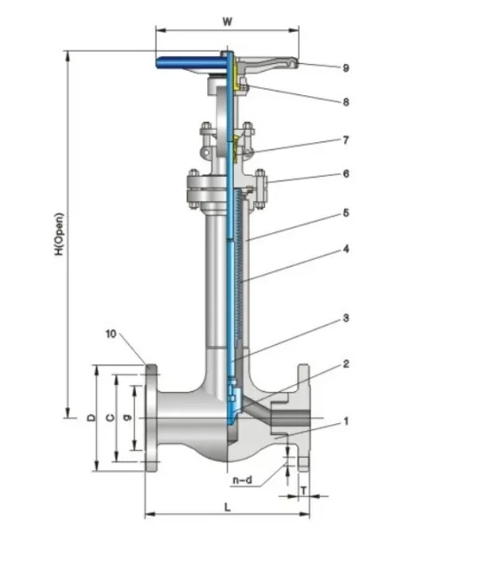
The extended bonnet and stem arrangement need space. ZGV publishes these selected Class 150 bellows globe dimensions.
| Catalogue size | Listed L mm | H open mm | Listed weight kg |
|---|---|---|---|
| NPS 1/2 | 108 | 420 | 8 |
| NPS 1 | 127 | 486 | 14 |
| NPS 2 | 203 | 615 | 20 |
Scroll the table horizontally on a small screen.
Source: ZGV product 2550 dimension table. The source drawing measures H open from the pipe centreline to its indicated upper reference. Complete operator clearance and the room to remove parts require the approved assembly and maintenance drawings.
A valve can fit between the pipe flanges and still be awkward to operate beneath a platform. A closed-position model may also miss interference when the stem rises. The maintenance review should establish which assembly is removed and the space needed to withdraw it.
The operator arrangement is part of that review. Handwheel reach, any stem extension, insulation and access for inspection should be agreed for the actual installation. A catalogue height from another size or pressure class is insufficient.
Confirm whether the duty is isolation or regulation
Bellows sealed describes a stem sealing method. It does not identify the flow characteristic of the closure element. For example, Spirax Sarco distinguishes its flat-disc BSA isolation version from a BSAT version with a throttling plug. The distinction illustrates why the disc or trim must be named when regulation is required. BSA and BSAT product explanation
For a ZGV enquiry, state whether the valve will isolate the line or make repeated flow adjustments. Ask for confirmation that the proposed closure arrangement, stem travel and bellows duty match that use. A stem seal upgrade does not, on its own, establish a suitable regulating design.
Put the evidence beside the requirement
| Requirement | Information needed for review |
|---|---|
| Control leakage around the stem | Bellows and backup sealing arrangement, materials and the applicable external-leakage evidence |
| Meet internal shutoff requirements | Separate seat test, direction, conditions and acceptance requirement |
| Withstand the operating movement | Defined travel and cycle-count basis at the stated pressure and temperature |
| Suit the fluid | Complete wetted materials and review of relevant impurities and cleaning media |
| Remain accessible in the line | Open envelope, maintenance removal space and operator arrangement |
| Support planned maintenance | Replaceable assembly scope, identification, spares and the proposed inspection basis |
Scroll the table horizontally on a small screen.
The bellows gate, Class 150/300 bellows globe and Class 800 bellows globe entries provide concrete starting configurations. Send the operating movement and service conditions with the product reference. A useful technical reply should make the sealing paths and life assumptions explicit enough to review before the order is placed.
Include the valve RFQ worksheet with the enquiry. Add the required stem travel, movement pattern and cycle-count definition, and identify the stem and seat leakage requirements separately. You can discuss the bellows valve enquiry with ZGV.