
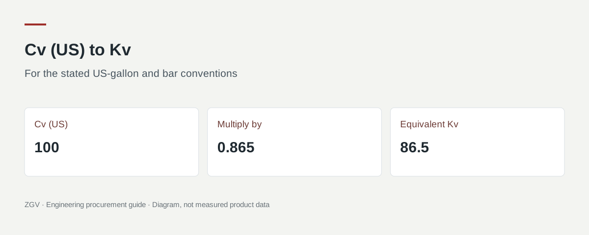
For the usual US-gallon Cv and bar-based Kv conventions, Kv ≈ 0.865 × Cv and Cv ≈ 1.156 × Kv. A quoted Cv of 100 therefore corresponds to a Kv of approximately 86.5. This converts the coefficient convention. It does not change the valve, establish its pressure rating, or prove that two proposed valves will perform alike in the installed system.
Before comparing quotations, confirm the coefficient convention, the exact valve configuration and the opening position. Then compare the stated capacity with the actual operating cases. A number labelled only “flow coefficient” leaves too much unresolved.
What Cv, Kv and Kvs describe
Cv and Kv express flow capacity using different reference conditions and units. A coefficient belongs to a particular flow passage at a particular opening. It is separate from the nominal pipe size and the pressure class.
| Label | Convention to confirm | What the quotation should identify |
|---|---|---|
| Cv | Usually US gallons per minute of water at a 1 psi pressure differential | US or Imperial gallon convention, valve configuration and opening |
| Kv | Cubic metres per hour of water at a 1 bar pressure differential | Bar-based convention, valve configuration and opening |
| Kvs | Stated Kv at the fully open position | The offered size and trim, not merely a family-wide maximum |
| Required Kv or Cv | Capacity needed by the application | Fluid properties, flow and pressure conditions used in the calculation |
Spirax Sarco distinguishes these conventions and warns that both US and Imperial Cv exist. The common 0.865 conversion applies to US Cv; it must not be applied to an Imperial-gallon figure without checking the convention. Source: Spirax Sarco, Control Valve Capacity.
For procurement, request a notation such as “Cv (US), fully open, product configuration X, data-sheet revision Y.” That is more useful than adding further decimal places to an unidentified number.
A compact Cv-to-Kv conversion table
The following values are calculations using Kv = 0.865 × Cv. They are conversion examples, not measured capacities of ZGV valves.
| Cv (US) | Equivalent Kv, rounded |
|---|---|
| 10 | 8.65 |
| 25 | 21.6 |
| 50 | 43.3 |
| 100 | 86.5 |
| 250 | 216 |
| 500 | 433 |
To convert in the other direction, divide Kv by 0.865. For example, Kv = 40 gives Cv ≈ 46.2. The factor is also stated in the Fisher valve-sizing reference. Source: Fisher, Catalog 12, equation constants and flow-coefficient conversion, PDF page 3.
Keep unrounded values in a comparison worksheet and round the displayed result to suit the source data. Converting a catalogue value reported to two significant figures into six decimal places does not improve the underlying evidence.
A liquid calculation, with its limits visible
For a simplified, turbulent, non-choked, single-phase liquid calculation without attached-fitting corrections:
Kv = Q × √(SG / Δp)
Here, Q is liquid volume flow in m³/h, Δp is the pressure drop across the valve in bar, and SG is the liquid density relative to the applicable reference water density. For the water example below, assume SG = 1.
Suppose an engineer assigns a valve a maximum pressure-drop allowance of 0.25 bar at a flow of 20 m³/h. Under those stated assumptions:
Required Kv = 20 × √(1 / 0.25) = 40.
The equivalent required Cv is approximately 46.2. These are hypothetical inputs chosen to show the arithmetic. They are not ZGV test data, a product selection, or a guarantee of system flow. Spirax Sarco explains the relationship between liquid flow, differential pressure and Kv in its water-system sizing guide.
For a first comparison, an offered Kv below 40 would not satisfy that particular simplified calculation at the specified opening. A value above 40 still leaves other acceptance questions: material compatibility, pressure-temperature limits, installation, operating range and any required control behaviour. Record the calculation as one check in the selection process.
When a simple conversion is enough, and when sizing is needed
There are two separate tasks:
- Convert an existing coefficient. Both offers identify valid coefficients for the configurations being compared. Put them in one convention before comparing the figures.
- Determine the required coefficient. The process conditions must be evaluated to establish what the application needs. A conversion factor cannot supply missing operating data.
A gas, steam or compressible-flow calculation needs its appropriate model and pressure basis. Viscous liquids, attached reducers, and conditions involving choking or a change of phase also need additional consideration. Fisher's reference describes piping-geometry and Reynolds-number corrections and the need to evaluate limiting liquid pressure drop. A short conversion table does not replace those checks.
Swagelok's Cv calculator illustrates the distinction: calculating flow or Cv requires additional fluid, pressure and temperature inputs, and liquid and gas calculations are separate. The useful question for the supplier is “which model and operating case did you use?”, rather than “which converter did you use?”
Compare the actual offers on one basis
Consider this fictional comparison. No product sizes or performance are attributed to ZGV.
| Field | Offer A | Offer B | Clarification needed |
|---|---|---|---|
| Coefficient | Kv 80 | Cv 100 | B converts to Kv 86.5 if it uses US Cv |
| Opening | Fully open | Not stated | Request B's opening position |
| Configuration | Identified trim and bore | Family brochure only | Tie B's value to the offered build |
| Data basis | Referenced data sheet | No reference | Request the source and revision |
| Operating cases | Normal case supplied | Not supplied | Ask both suppliers to assess the same cases |
The converted values alone suggest that B's stated coefficient is higher. The missing opening and configuration information prevents a reliable purchase comparison. Do not resolve that uncertainty by assuming B means fully open or by borrowing a coefficient from a similar model.
If the duty is continuous control, ask for capacity against travel or opening and a review of the operating range. A fully open coefficient cannot show where the valve will operate at the minimum required flow. If the duty is isolation, confirm the fully open loss at the required flow and assess shutoff requirements separately.
For ball valves, full bore and reduced bore should remain distinct quotation fields. Bore dimensions help describe the passage; a diameter or area ratio alone is not a verified Cv ratio.
Flow data to include in a valve RFQ
Send a small operating-case table rather than one unqualified “design flow” value. Leave unknown values visibly open for engineering clarification.
| RFQ item | What to provide or request |
|---|---|
| Operating cases | Minimum, normal, maximum and any relevant start-up case |
| Fluid | Identity, composition and phase; identify any solids or unusual behaviour |
| Flow | Value and unit; state whether a gas volume is actual or referred to defined standard conditions |
| Pressures | Upstream and downstream values at each case, their gauge or absolute basis, and valve pressure-drop allowance |
| Temperature and properties | Operating temperature; density and viscosity where relevant, with their source |
| Installation | Line size and internal diameter, nearby reducers or other fittings, and available envelope |
| Valve duty | Isolation or control, operating range, required shutoff and permitted leakage basis |
| Supplier response | Exact configuration, Cv/Kv convention, opening, data reference, calculation assumptions and unresolved conditions |
Ask the supplier to distinguish an established catalogue coefficient from an estimate or a value requiring further verification. If the response offers an alternative bore, size or trim, request its own coefficient and installation data. Do not keep the original flow figure beside an alternative build without checking that they belong together.
Preparing a ZGV enquiry
Start with the ZGV ball-valve family and identify the relevant product configuration. For example, the published references distinguish product 2511, a Class 150/300 floating ball valve, from product 2514, a Class 150/300 trunnion-mounted ball valve. Those catalogue identities do not establish a universal flow coefficient for either design.
Use the industrial valve selection guide and RFQ checklist to assemble the wider purchase requirements. Then send ZGV the operating cases and requested flow-data basis. Ask which coefficient data are available for the offered configuration and what further engineering information is required.
For an operating-cost comparison after a suitable configuration has been established, use the separate pressure-loss and pumping-energy worked example. It addresses the system conditions needed to translate a pressure-loss difference into an energy calculation.
Download the ZGV valve RFQ template and attach the operating cases, configuration identity and required documents to your enquiry.