
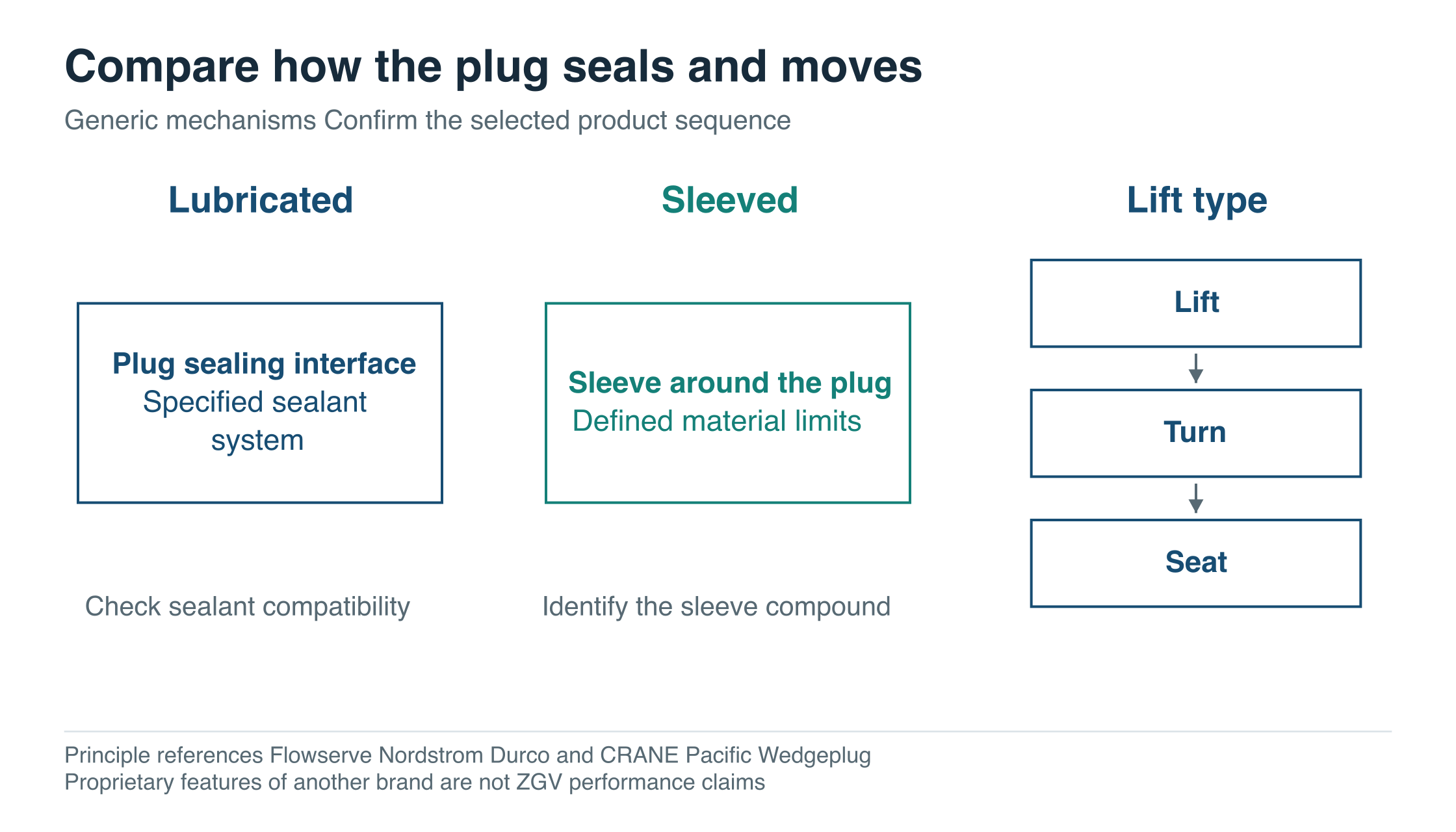
A plug valve quotation should explain how the plug seals and how it moves. “Quarter turn” alone can conceal a lubricated metal interface, a sleeve surrounding the plug or an arrangement that lifts before turning.
Those mechanisms create different questions about materials, maintenance and operation. A useful shortlist identifies the mechanism first, then checks it against the medium and the required flow path.
Start with how the seal is established
Lubricated designs
A lubricated plug valve uses a specified sealant or lubricant system as part of its operating and sealing arrangement. Flowserve’s Nordstrom bolted-gland steel description, for example, identifies a grooving system that distributes pressurised sealant to the seating surfaces. That is a manufacturer-specific design explanation, rather than a maintenance instruction for another valve. Flowserve lubricated plug valve
The buying implications are concrete. The proposed sealant needs to suit the medium and temperature, its presence needs to be acceptable to the process, and the maintenance arrangement needs to be practical for the site. A lubricant description without a grade or compatibility basis leaves these questions open.
ZGV lists a pressure balanced side-mounted oil sealed plug valve. A technical enquiry for this mechanism should identify the proposed sealant system and obtain the actual construction, material schedule and rating for the service. These are the details needed to compare a defined offer.
Sleeved designs
A sleeve provides a sealing interface around the plug in a sleeved design. Its composition and construction matter because they are part of the wetted and mechanically loaded system. Flowserve’s Durco range includes non-lubricated sleeved plug valves, illustrating the distinction from the lubricated mechanism above. Flowserve Durco product family
ZGV’s flanged sleeved plug valve entry lists alternative body and plug materials, along with dimensions. Its public materials table does not separately identify the sleeve compound. That missing field matters: the buyer should ask for the sleeve material and its complete service limits instead of inserting a generic PTFE assumption.
Likewise, “non-lubricated” should not become a promise of no inspection, no adjustment or unlimited life. The offered design still needs a maintenance basis and confirmation that the process will not compromise movement or sealing.
Lift designs
A lift plug arrangement separates lifting from rotation as part of the operating sequence. CRANE’s Pacific Wedgeplug literature provides a specific example of lifting the plug, rotating it and reseating it. That product’s proprietary seat protection, purging and operating features are not implied for every lift plug valve. Pacific Wedgeplug brochure, pages 5 and 8
ZGV lists a lift type metal seated plug valve with manual, worm gear, pneumatic and electric operating options in its technical table. The required sequence and force or torque basis should be confirmed for the proposed configuration. An operator must produce the movements the mechanism requires, including seating, rather than merely rotate an output shaft through 90 degrees.
Swipe or scroll horizontally to see the full diagram.
The mechanisms need different evidence
| Proposed mechanism | Information that makes the offer assessable |
|---|---|
| Lubricated | Sealant system and grade; process compatibility; required service provisions and maintenance basis |
| Sleeved | Exact sleeve material and construction; limits for the medium, pressure and temperature; adjustment and replacement scope |
| Lift type | Movement sequence; sealing arrangement; required lift and rotational loads; operator and any service connections |
Scroll the table horizontally on a small screen.
A process that cannot tolerate sealant entering the medium may narrow the choice early. A line prone to deposits needs evidence that the proposed movement and sealing arrangement can address those deposits. These constraints make the mechanism comparison useful before price and installation details are finalised.
Leave space for the lift operator
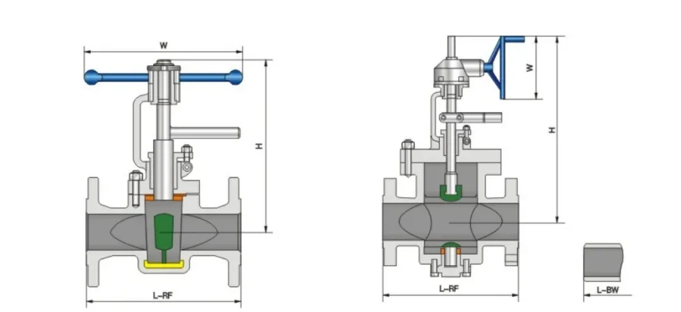
The movement sequence has a layout consequence: the selected operator and moving assembly need an identified envelope. ZGV’s lift plug table provides these entries for two sizes and two pressure classes.
| Catalogue Class | Size | Listed L mm | Listed H mm | Weight kg |
|---|---|---|---|---|
| 150 | NPS 2 | 178 | 310 | 23 |
| 300 | NPS 2 | 216 | 310 | 28 |
| 150 | NPS 3 | 203 | 395 | 32 |
| 300 | NPS 3 | 282 | 395 | 39 |
Scroll the table horizontally on a small screen.
Source: ZGV product 2573 X43Y dimension table. L uses the catalogue column headed L-RF / L-RF+BW. RF denotes raised-face flanged ends and BW butt-weld ends. Confirm the proposed end pattern on the approved drawing. The illustrated H starts at the pipe centreline; it is not a verified powered-assembly height.
At NPS 2, changing from the listed Class 150 to Class 300 entry changes L by 38 mm while both rows retain H of 310 mm. At NPS 3, L changes by 79 mm while both H entries remain 395 mm. Pressure class therefore does not provide a universal multiplier for either the installation length or the operator envelope.
Request the drawing for the exact end connection and operating arrangement, with the lift and rotation sequence identified. If a gearbox or powered actuator is offered, review that assembly rather than substituting the manual catalogue envelope. Maintenance withdrawal space should be shown separately from the ordinary operating envelope.
Swipe or scroll horizontally to see the full diagram.
Keep the material choice attached to the offered assembly
The ZGV sleeved and lift entries list several alternative body materials, including WCB and CF8M, and alternative gasket and packing materials. A list of alternatives is not a bill of materials for one valve.
The quotation should identify the actual body, plug, seating or sleeve material, stem seals and gaskets selected for the duty. Where a surface treatment is important, it should be specified separately rather than inferred from the base alloy. This is especially important when suppliers use similar product names for more than one trim.
For a difficult medium, explain the failure mechanism the selection is intended to address. Abrasion, corrosion, hardening deposits and crystallisation are different concerns. A request for “heavy duty plug valve” does not tell the supplier which of them needs evidence.
Multiport valves need a port state drawing
A three-way or four-way plug valve adds a second selection task: defining which connections are open in each operating position. ZGV’s three-way and four-way plug valve entry is a starting point for that discussion. The number of external ports does not identify the internal passage pattern or what happens while the plug moves.
For example, a buyer planning to switch one feed between two destinations could submit the following hypothetical requirements for supplier confirmation.
| Required state or transition | What the supplier must confirm |
|---|---|
| Position 1 routes feed A to outlet B | Passage drawing and isolation condition of outlet C |
| Position 2 routes feed A to outlet C | Passage drawing and isolation condition of outlet B |
| Transition between the positions | Whether paths overlap, become blocked or create another connection during travel |
| A requested all-closed position | Whether that state exists in the proposed design and how it is identified |
Scroll the table horizontally on a small screen.
This table does not assert that a particular ZGV multiport valve offers every listed state. It defines the questions that a port drawing must answer. The permitted intermediate connections may matter as much as the end positions when fluids or destinations must remain separate.
Specify required flow direction, port labels, switching sequence and acceptance requirements for each relevant connection. The operator indication should correspond to those agreed states. A generic open/closed indicator may be inadequate for a routing task with more than two meaningful positions.
Specify the mechanism and flow path in the enquiry
For a two-way valve, identify the sealing mechanism, service conditions, end connections and actual materials, then obtain the movement and load information for the operator. For a multiport valve, add the port-state drawing and transition requirements before approving the offer.
Compare lubricated, sleeved and lift proposals using their identified materials, drawings and operating sequences. If an alternative changes the sealant, sleeve or movement, ask which project requirement it addresses and record that change in the offer. The port-state drawing should remain part of the agreed configuration for a routing valve.
Use the valve RFQ worksheet for the service conditions. Attach the required movement sequence and, for a routing valve, a labelled port-state and transition schedule. You can send the plug valve and port-state enquiry to ZGV.