
A ball valve can leak through its closed flow path, around the stem, at a body joint, or at a pipe connection. These are different faults. Before requesting a repair kit or replacement, identify the observed path, confirm how the valve position was established, and record the pressure and temperature conditions. A description such as “the valve is leaking” is not yet enough to select a remedy.
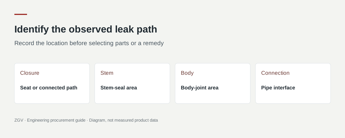
This guide helps operators, maintenance planners and buyers prepare that investigation. Any physical intervention must follow the plant's isolation procedure and the instructions for the actual valve and actuator. Isolate and verify the release of process pressure, trapped cavity pressure and stored actuator energy before opening, dismantling or adjusting a pressure-containing assembly. Manufacturer instructions are design-specific; a generic tightening angle or bolt torque is not a substitute.
First separate internal and external leakage
| Observation | Path to investigate | What the observation does not prove |
|---|---|---|
| Flow or pressure recovery downstream of a valve expected to be closed | Through the closure, a bypass, or another connected source | That the seat is damaged |
| Fluid or an instrument reading localised around the stem seal | Stem packing or stem-seal area | That the valve also leaks through its seat |
| Leakage at a body split, cap or cover | Body-joint sealing area | That the nearby pipe flange is the source |
| Leakage at the mating pipe flange, thread or weld | End connection and installation | That a body gasket or seat kit will resolve it |
| Position indication stops short or conflicts with other indications | Travel, coupling, actuator or indication | That adding closing torque is appropriate |
Do not expose a downstream opening to establish a leak path. Use the site's approved test arrangement and instruments, with the fluid and pressure hazards assessed. Pressure recovery alone also needs context: another supply, bypass, trapped volume or temperature change may affect the reading.
Photograph the valve identity and mark the suspected leak location on a simple sketch. Keep “observed at the stem” separate from “confirmed stem-seal failure” until the investigation supports the latter.
A closed indication does not establish a sound closure
A control signal, limit-switch indication and physical valve position describe different parts of the assembly. If a leak appeared after actuator work, document what changed before assuming that the seats have failed.
Have the responsible technician check the applicable valve and actuator instructions, the travel and coupling arrangement, and the configured end positions. Valmet's M1/M2 ball-valve troubleshooting table identifies incorrect actuator stops, positioner setting and damaged sealing components as different possible causes of leakage through a closed valve. Source: Valmet, Neles M1/M2 instructions, Table 8.
Record which check was completed and its result. “Closed command received” should not become “mechanical closure verified” in the repair request. Conversely, a confirmed travel problem should not be used to dismiss an external leak that requires its own investigation.
Internal leakage: distinguish contamination from damaged parts
Debris, a damaged ball or seat, an unsuitable service condition and incomplete travel can lead to similar reported symptoms. The timing helps determine what to investigate, but it does not establish the cause on its own.
| History to record | Investigation it can help prioritise |
|---|---|
| Leakage began during commissioning or after nearby pipework | Cleanliness, foreign material and installation records |
| Leakage developed after an actuator or positioner intervention | Travel, settings, coupling and actual valve position |
| Leakage followed a temperature, pressure or medium change | Offered configuration and its approved service envelope |
| Leakage increased gradually with operation | Sealing-surface condition and service history |
| A repaired valve leaks again | Component identity, assembly, test result and whether the original cause was resolved |
Emerson's KTM trunnion-valve manual explains that hard foreign material can damage the ball and seat, and that seat-sealing investigation may involve the ball, seats and seals. These are examples of why inspection must follow the actual construction. They do not establish the failure mode or repair method of a ZGV valve. Source: Emerson, KTM series E01 manual, maintenance and installation sections.
Do not prescribe repeated cycling to force debris through a suspected damaged sealing area. Let the plant and manufacturer determine whether operation, testing, removal or inspection is appropriate for that case.
Stem leakage: identify the sealing arrangement before adjustment
The stem-to-atmosphere sealing system may use packing, O-rings or a different arrangement. An external leak at this location requires the applicable seal and adjustment information, rather than a universal instruction to tighten a gland by a quarter turn.
The distinction is visible in manufacturers' own documents. Swagelok describes an O-ring stem seal requiring no packing adjustment on its SK series. Valmet explains different behaviour for packing arrangements and cautions that excessive force can damage V-rings. Sources: Swagelok SK-series catalogue, Valmet M1/M2 instructions, gland-packing section.
For the maintenance enquiry, provide the product identification, seal arrangement if known, leak location and conditions, previous adjustments and any resulting change in operating torque. Ask whether adjustment is permitted, which procedure applies, and when seal replacement or further inspection is required. Keep the response attached to that valve's work order.
Body-joint and pipe-connection leaks need separate records
A body joint belongs to the valve assembly. A mating pipe flange, threaded connection or site weld is an installation interface. Their parts, procedures and acceptance checks may be different even when the visible leakage is only a few centimetres apart.
Record the exact joint, gasket or connection identification if available, and whether the valve was recently installed or reassembled. Include the applicable assembly drawing and the maintenance record. Ask the responsible engineer to review alignment, support and any relevant piping loads where the installation evidence warrants it.
Do not copy a bolt torque from another size, material, gasket or manufacturer. Emerson's KTM instructions require clean, undamaged mating flanges and gaskets and warn against excessive closing force. Its maintenance guidance is tied to the identified valve and depressurised condition. Source: Emerson, KTM two-way, three-way and V-port instructions.
A repair request should state whether the proposed work covers the valve body joint, the pipe connection, or both. Otherwise, a quotation for a seat kit can leave the actual external leak untouched.
Pressure, temperature and leakage acceptance are different fields
For a valve that leaked after an excursion, collect the actual pressure-temperature history and the offered body, seat, packing and seal configuration. A flange-class label alone cannot establish that every component was suitable for the event. The ZGV guide to Class 150 pressure-temperature ratings explains why the designation needs its material and temperature context.
Also distinguish a field observation from a specified acceptance test. “No visible leak at this instrument's sensitivity” is different from an agreed seat-test result under a named procedure. Record the test medium, pressure, direction, duration, measurement method and acceptance requirement before comparing reports. Use the inspection and leakage-testing procurement guide for those purchase-document questions.
Where trapped liquid or a particular isolation arrangement is relevant, review it separately with the manufacturer. The cavity pressure-relief guide and DBB/DIB pressure-case guide address those design questions; neither substitutes for identifying the observed leak.
An evidence pack for the repair or replacement decision
Use this checklist to avoid repeated clarification messages:
| Evidence | Minimum useful description |
|---|---|
| Valve identity | Manufacturer, tag, model, size, class, serial/order reference and nameplate photo |
| Observed path | Marked photo or sketch; external location or defined internal test boundary |
| Operating case | Medium, temperature, upstream/downstream pressures, phase and relevant operating stage |
| Timing | First observed, intermittent or continuous, and relevant event before it began |
| Assembly | Manual or actuated, actuator identity, position evidence and recent setting changes |
| History | Installation, flushing, commissioning, service changes, repair and adjustment records |
| Assessment | What has been checked, by whom, under which procedure, and the findings |
| Requested decision | Further inspection, approved repair scope, suitable spares or replacement proposal |
For example, a fictional request might report: “Tag BV-104 has an external leak localised at the stem area after actuator work. Valve and actuator identity photos are attached. The recorded operating case and intervention history are listed. Please identify the applicable inspection procedure and information needed before a repair kit or replacement is selected.” This communicates a real observation without inventing a root cause.
For a ZGV valve, send the evidence pack to ZGV with the actual product reference. The ball-valve family page can help identify the catalogue family, but visual similarity alone does not establish interchangeable parts or a supported repair method.
The repair decision should close three items: the confirmed leak path, the approved scope of work, and the applicable return-to-service acceptance record. Keeping those items explicit helps a buyer obtain the right technical reply and avoids replacing parts before the fault has been defined.
Download the ZGV valve RFQ template and attach the operating cases, configuration identity and required documents to your enquiry.
Catalogue references for your enquiry
2511: Two piece floating ball valve Class150/300; 2514: Two piece fixed ball valve Class150/300; 2519: Two piece metal hard sealed ball valve Class150/300/600. These published entries help identify a proposed configuration. They do not confirm interchangeability, an installation or repair procedure, or parts availability for the actual assembly. Ask ZGV to confirm the applicable documents and supply scope.