
Before installing an industrial valve, match its nameplate and assembly records to the approved drawing, service conditions and installation instructions. Then verify the pipe interface, cleanliness, operating clearance and operator configuration. Commissioning needs a separate, approved test scope with recorded results. A valve that moves on the workshop floor has not yet demonstrated its performance in the installed system.
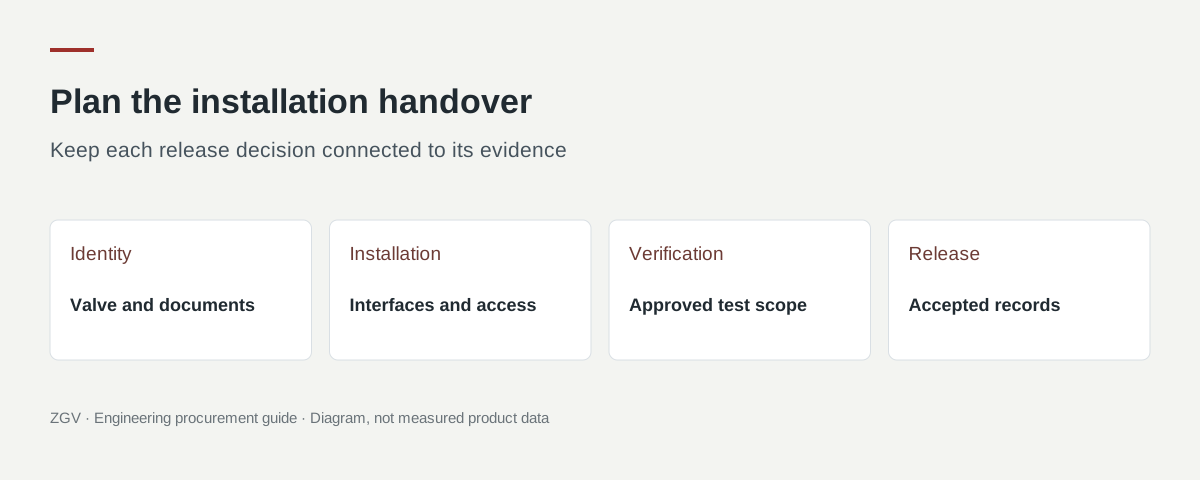
This checklist helps procurement, construction and commissioning teams agree what evidence is needed at each handover. It covers isolation valves and associated operators at a planning level. The supplied valve and actuator manuals, project specifications and approved site procedures govern the actual work. Safety valves, special-service equipment and safety instrumented functions require their own applicable procedures.
Separate the three release decisions
Receiving, installation and commissioning answer different questions. Use the receiving inspection and storage guide to establish what arrived and how it was preserved. The checks below start when the identified assembly is being released for installation.
| Decision | Question to close | Useful release evidence |
|---|---|---|
| Ready to install | Is this assembly suitable and prepared for this location? | Approved identity, drawing, service basis, condition and installation method |
| Ready to commission | Is the installed assembly mechanically and functionally ready for the planned tests? | Completed installation checks, approved operator setup and resolved relevant holds |
| Ready for service | Were the specified checks completed and remaining restrictions accepted? | Test results, accepted settings, deviation dispositions and authorised release |
These are suggested record categories, not a universal inspection standard. The project should name the responsible reviewer for each decision. An accepted valve delivery can still have an unresolved installation interface. A mechanically complete installation can still await a control-system test.
1. Identify the actual assembly and its instructions
Record the valve tag, manufacturer, model, size, rating, serial or other available unique identifier, and the approved drawing revision. Identify an actuator, gearbox and accessories separately where fitted. A site tag locates an item in the plant; it should also lead to the manufacturer's assembly records.
Check the operating medium and required pressure-temperature conditions against the approved assembly. Include relevant seat, seal and operator restrictions. A pressure class printed on a body does not establish suitability for every fluid or temperature. The pressure-temperature rating guide explains that distinction.
Obtain the instructions for the supplied construction. Spirax Sarco's M70i/M80i manual, for example, treats suitability, mounting and cleanliness as installation checks for those identified products. Its instructions belong to that valve design, rather than every industrial ball valve. Spirax Sarco installation manual, sections 1 and 3
If the drawing, nameplate and order disagree, record the affected field and obtain a disposition. Changing the checklist to match the delivered item does not resolve whether the item meets the approved requirement.
2. Check the complete pipe interface
Nominal size and bolt-hole alignment are an incomplete fit check. Confirm the dimensions and contact surfaces that matter to the actual connection.
| Interface item | What the installation team should establish |
|---|---|
| Face-to-face or end-to-end length | Approved dimension, pattern and available installation space |
| End connection | Correct flange facing, threaded or welded-end detail and applicable drawing |
| Internal clearance | Pipe, flange and adjacent equipment allow the required closure-element movement |
| Joint materials | Correct specified gasket or other sealing arrangement for this design |
| Bolting | Required type, length, engagement and tightening procedure |
| Pipe support and alignment | The approved arrangement avoids using the valve to pull misaligned pipework into place |
| External access | Space for the handle, rising stem, operator, manual override and planned maintenance |
Butterfly valves deserve a specific disc-clearance check. Crane's Center Line instructions address pipe/flange compatibility and the disc's movement envelope. They also specify a sealing arrangement that omits additional flange gaskets for the covered installation. That product example shows why an instruction to add a gasket to every flanged valve is unreliable. Follow the actual supplied design. Crane Center Line manual, pages 3–5
For replacement work, retain a connection schedule and the approved drawing. The RF versus RTJ checklist and face-to-face retrofit guide address the detailed comparison before the installation team reaches the pipework.
3. Agree cleanliness and flushing before exposure
Define who releases the line as ready, how cleanliness is demonstrated and which components require protection during cleaning or flushing. Identify the cleaning medium, its compatibility with the supplied materials and the approved arrangement for the valve and any temporary equipment.
Keep these as separate questions:
- Has storage protection been removed at the appropriate stage?
- Are the valve and adjoining pipework free of unacceptable debris?
- Is the valve permitted to remain installed during the proposed cleaning or flushing activity?
- What position, protection or temporary arrangement does its manufacturer require?
- Who confirms the final condition before normal operation?
Do not turn a general checklist into a universal instruction to flush through every valve fully open. Different constructions and cleaning duties need different arrangements. A line-cleaning record should identify what was actually done and any component removed or protected. Following cleaning, restore the approved configuration and account for temporary items under the project procedure.
4. Confirm direction and position for the offered design
Record the required flow direction, any pressure-direction limitation and the manufacturer's installation orientation. Keep those fields distinct. A valve may have different requirements for normal flow, reverse pressure and the condition under which it must shut off.
Check any body arrows against the supplied documentation. If an arrow's meaning is unclear, seek clarification before installation. A catalogue description such as bidirectional should be tied to the actual construction and service requirement.
Likewise, use the prescribed closure-element position during installation. The correct position for one ball or butterfly design should not be carried into another assembly's work instruction. The vertical check-valve guide covers a common case where pipe orientation alone cannot settle the installation question.
5. Preserve the valve and actuator setup
For an automated assembly, identify the accepted valve, actuator, mounting parts and accessory configuration. Verify the supplied electrical or pneumatic information against the installation design. Record the applicable travel, limit, torque/thrust and feedback settings rather than relying on an unlabelled photograph of a display.
A commissioning plan should also say which changes require renewed verification. Rotork's safety manual for identified IQ/IQT actuators with the Stayput safety function requires commissioning or verification at specified installation and disconnection events. That is a product-specific example of configuration control. The manual does not qualify an unspecified actuator or make that function standard on ZGV equipment. Rotork IQ/IQT safety manual, section 4.1
Use the valve cause-and-effect guide to define the required response to each relevant event. Any field simulation must be authorised and conducted under a controlled test procedure. An informal loss-of-air or power test can affect connected plant equipment.
6. Write the commissioning test sheet before the test
Each test needs an identified condition, expected result and acceptance basis. Keep a movement check, a control/indication check and a pressure or leakage test as separate records when they answer different requirements.
| Record field | Information to enter |
|---|---|
| Assembly tested | Tag, valve/operator identity and accepted configuration revision |
| Test purpose | Movement, indication, event response, connection integrity or specified leakage requirement |
| Conditions | Applicable medium, supplies, load, pressure and temperature as required by the approved procedure |
| Acceptance basis | Project requirement, supplied manual or agreed test procedure and revision |
| Observed result | Actual measurements or observations, with units and relevant instrument identity |
| Open issue | Specific discrepancy, owner and required disposition |
| Release | Responsible person's decision and any remaining restriction |
The table is a record framework. It supplies no universal test pressure, hold time, leakage limit or tightening torque. Those values need the applicable design and approved procedure.
A successful no-load stroke records movement under the conditions tested. It does not establish seat tightness or adequate output against every process load. Similarly, an endpoint signal should be recorded for what it demonstrates. Use the inspection and leakage-testing guide to define the separate evidence needed for a leakage requirement.
Close a hold with evidence, not a checked box
Consider a fictional installation with a butterfly disc that cannot complete its travel during the approved clearance check. Record the interference and affected assembly. The next action is an engineering review of the valve, pipe/flange interface and accepted drawing. Increasing actuator force or changing a stop setting without approval could conceal the mismatch.
After an authorised correction, retain the revised document and repeat the affected checks. Record which earlier results remain valid. The closeout should show the issue, the accepted correction and the verification, so the operations team receives the actual installed configuration.
Prepare an installation-focused enquiry to ZGV
Start with the relevant ball-valve or butterfly-valve family. Include the required service, connection schedule, installation envelope and operator duty. If an existing valve is involved, add its identity, approved drawing and the specific unresolved interface.
Ask which installation documents, drawings and test records can be supplied for the offered assembly, and agree their scope in the quotation. Catalogue information provides a starting point; the supplier's response must identify the actual proposed build.
Send the valve and installation requirements to ZGV. Include the document revision and the decision you need: suitability confirmation, an interface drawing, an operator configuration or a proposed test scope. This lets the response address a defined installation task.
Download the ZGV valve RFQ template and attach the operating cases, configuration identity and required documents to your enquiry.
Catalogue references for your enquiry
2511: Two piece floating ball valve Class150/300; 2514: Two piece fixed ball valve Class150/300; 2564: Soft seal clamp butterfly valve Class150; 2567: Triple eccentric metal hard seal wafer or flange connection butterfly valve Class150. These published entries help identify a proposed configuration. They do not confirm interchangeability, an installation or repair procedure, or parts availability for the actual assembly. Ask ZGV to confirm the applicable documents and supply scope.